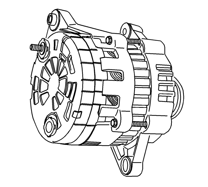
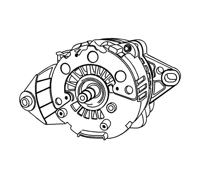
- Remove the generator. Refer to
Generator Replacement : LNQ → LF1 → LE5 .
- Mark a match line that cannot easily be removed on the end frame to make assembly easier.
- Pry off the plastic cover to expose the stator connections.
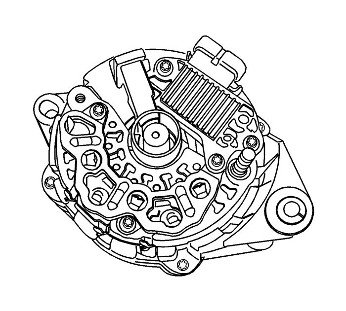
Note: If the stator connections are not welded, melt the lead. Avoid excessive heating, as it can damage the diodes in the rectifier bridge.
- Remove the stator connections from the rectifier bridge terminals by cutting the wires.
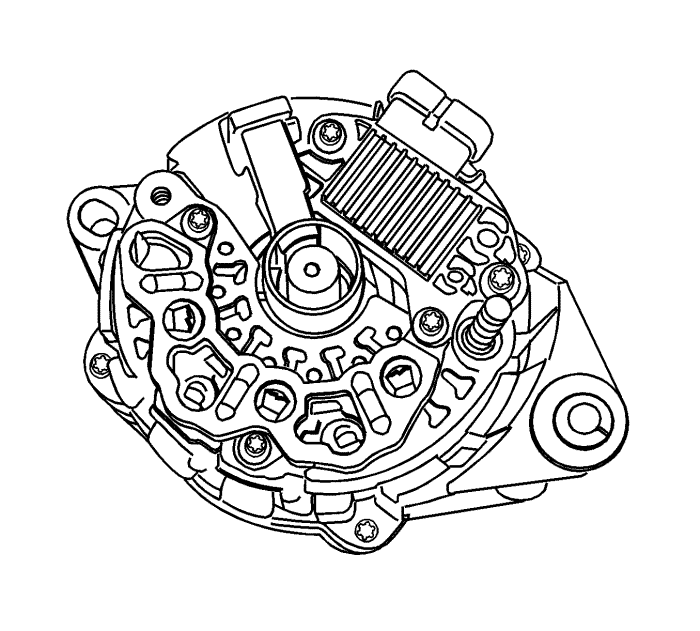
- Pry off the baffle.
- Remove the rectifier/regulator/brush holder assembly screws.
Note: If the brush can be reused, reassemble the brush to the holder with the retaining pin, after cleaning the brush with a soft, clean cloth.
- Remove the brush holder assembly and the regulator.
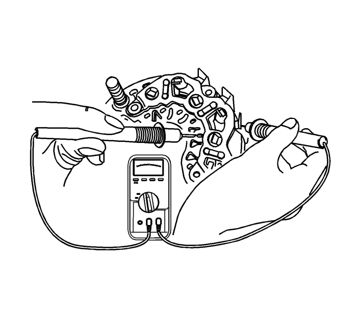
- Test the rectifier bridge by connecting the ohmmeter terminals to the bridge and the heat sink.
- Retest by connecting the ohmmeter terminals in reverse.
- Replace the rectifier bridge, if each reading is the same.
- Test the remaining two diodes after the above procedure.
Note: Some kinds of digital ohmmeters are not suited for the test of the bridge diode. In this case, consult the manufacturer regarding the test capacity.
- Test the diodes by connecting the ohmmeter terminals to the bridge terminal and the base plate. If the reading is the same, the rectifier bridge should be replaced.
- Remove the alternator through-bolts.
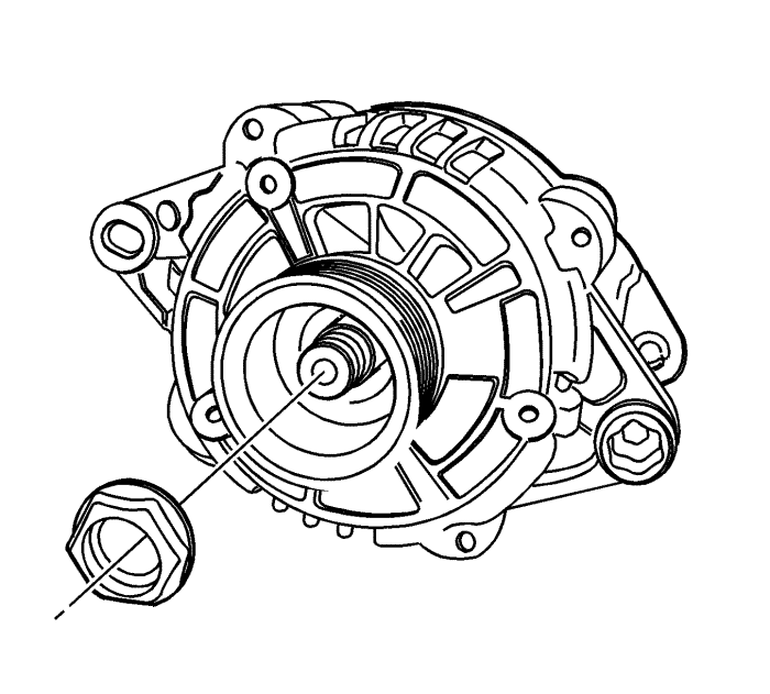
Note: The fastening torque of this nut is 81 N·m (60 lb ft) and may not normally be unfastened using hand strength.
- Move to the drive end of the alternator and remove the drive end bearing nut.
- Remove the pulley and the collars.
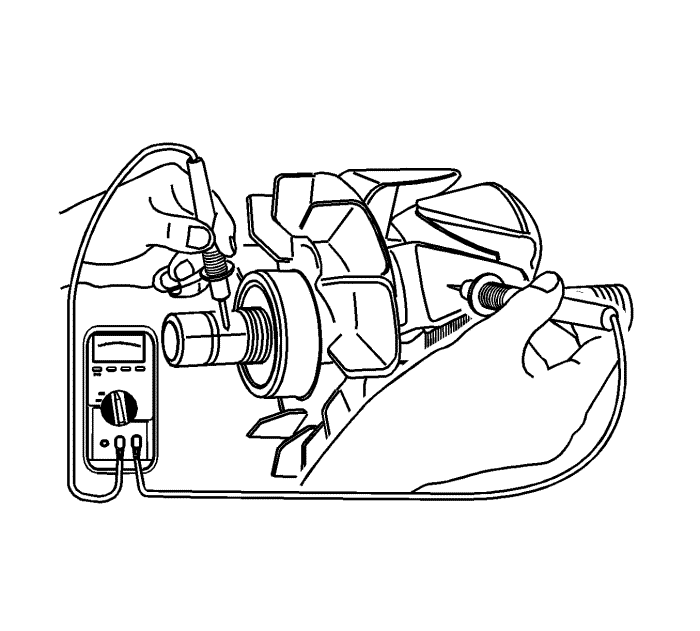
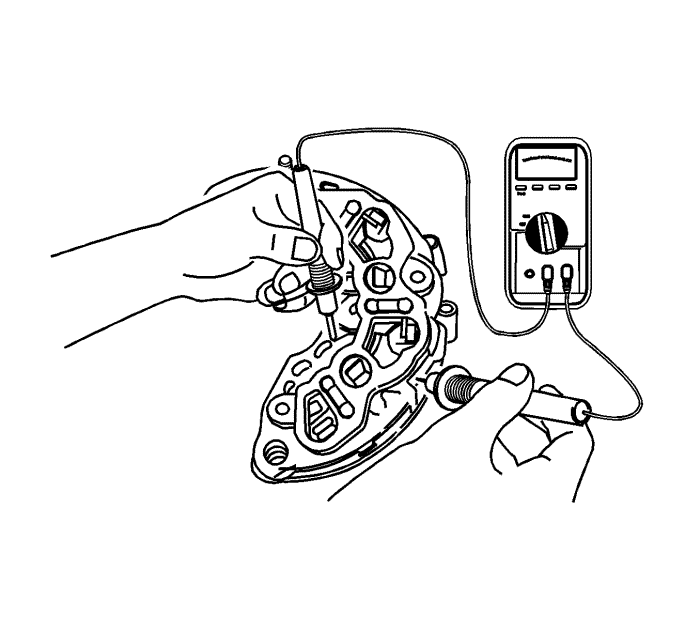
- Test the rotor for an open circuit using the ohmmeter with the drive end frame assembled. The reading should be sufficiently high, or the rotor must be replaced.
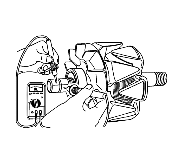
- Test the rotor for open and short circuits. The reading should be 1.7-2.3, or the rotor should be replaced.
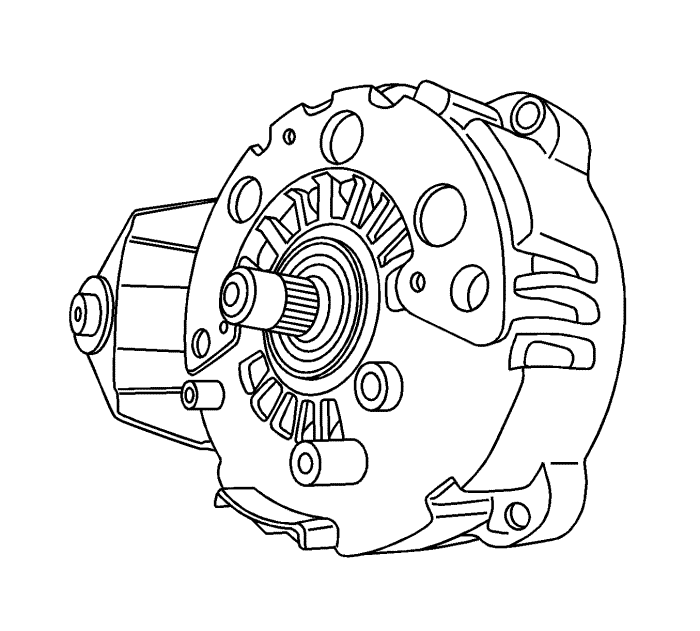
- Remove the drive end frame from the shaft.
- For vehicles with an internal alternator fan, remove the drive end frame and the fan.
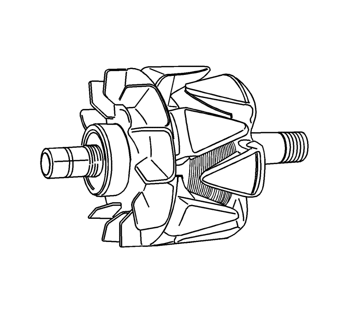
- Remove the rotor assembly.
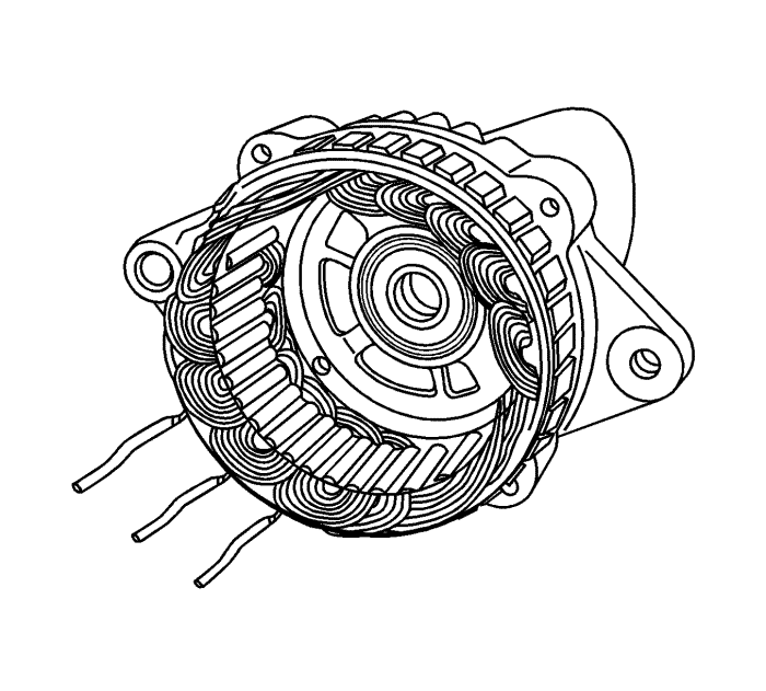
- Remove the stator.
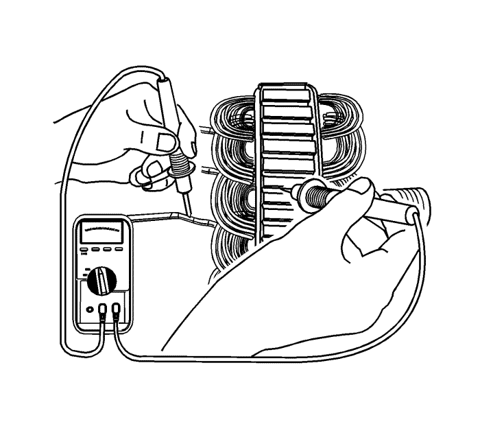
- Test the stator for an open circuit using the ohmmeter.
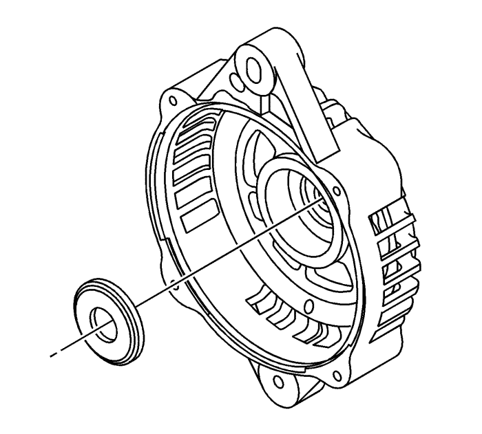
- Remove the ring in the slip ring end frame.


