Fuel Injector and Fuel Rail Replacement
Special Tools
EN-47909 Fuel Injector Bore and Sleeve Cleaning Kit
For equivalent regional tools, refer to
Special Tools : Diagnostic Tools Diesel .
Removal Procedure
- Relieve the fuel system pressure. Refer to Fuel Pressure Relief .
- Remove the fuel pipe shield. Refer to
Fuel Pipe Shield Replacement : LF1 or LFW .
- Remove the intake manifold. Refer to Inlet Manifold Replacement .
- Remove the fuel feed intermediate pipe. Refer to
Fuel Feed Intermediate Pipe Replacement : LF1 or LFW .
- Remove the foam insulator from the fuel rails.
- Remove the cylinder head. Refer to Cylinder Head Replacement - Left Side or Cylinder Head Replacement - Right Side
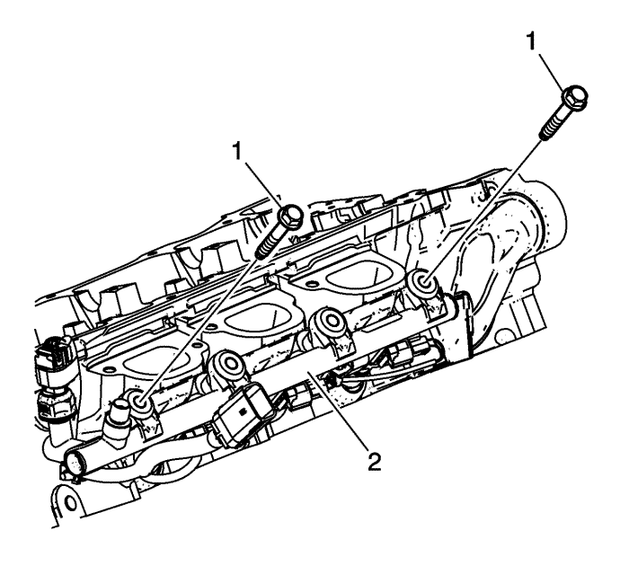
- Remove the bolts (1) from the bank 2 fuel rail.
- Remove the bank 1 fuel rail and injectors (1) as an assembly. Refer to
Cylinder Head Disassemble : LF1, LFW or LFX .
- Disconnect the bank 1 fuel injector electrical connections.
- If the bank 2 fuel rail or injectors are being serviced, remove them. Refer to
Cylinder Head Disassemble : LF1, LFW or LFX .
- Disconnect the bank 2 fuel injector and fuel pressure sensor electrical connections.
Note: The direct fuel injectors must be rebuilt whenever the injector has been released from the fuel rail or cylinder head.
- It is necessary to rebuild the fuel injectors. Refer to
Fuel Rail and Injectors Cleaning and Inspection : LF1, LFW or LFX .
Installation Procedure
- Clean the fuel injector bores using EN-47909 kit .
- Ensure that the fuel injectors have been properly rebuilt and lubricated. Refer to
Fuel Rail and Injectors Cleaning and Inspection : LF1, LFW or LFX .
- Connect the bank 2 fuel injector and fuel pressure sensor electrical connections.
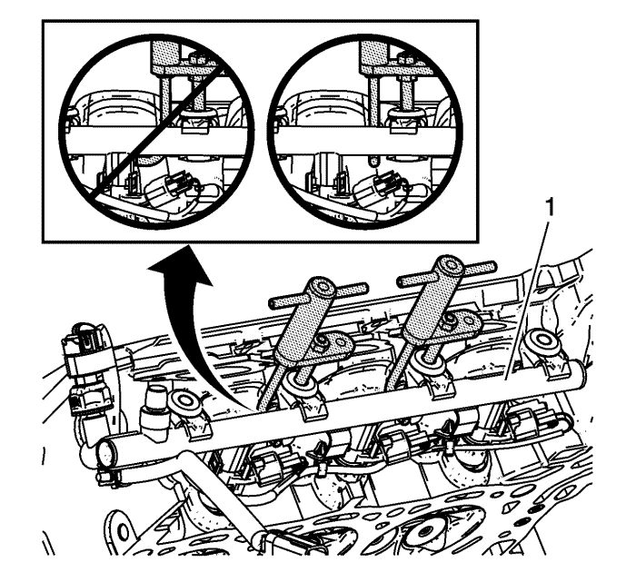
- Position the bank 2 fuel rail and evenly hand tighten the 2 outer fuel rail bolts to seat the injectors into the injector bores. Remove the bolts.
- Connect the bank 1 fuel injector electrical connections.
- Position the bank 1 fuel rail and evenly hand tighten the 2 outer fuel rail bolts to seat the injectors into the injector bores.
- Start and hand tighten the remaining fuel rail bolts.
Caution: Refer to Fastener Caution in the Preface section.
- Tighten the bank 1 and bank 2 fuel rail bolts.
| • | Tighten the inner fuel rail bolts to 10 N·m (89 lb in). |
| • | Tighten the outer fuel rail bolts to 10 N·m (89 lb in). |
- Replace any wire harness tie straps cut from the fuel rails.
- Install the cylinder head. Refer to Cylinder Head Replacement - Left Side or Cylinder Head Replacement - Right Side
- Install the fuel feed intermediate pipe. Refer to
Fuel Feed Intermediate Pipe Replacement : LF1 or LFW .
- Inspect for fuel leaks using the following procedure:
| 12.1. | Turn ON the ignition, with the engine OFF for 2 seconds. |
| 12.2. | Turn OFF the ignition, for 10 seconds. |
| 12.3. | Turn ON the ignition, with the engine OFF. |
| 12.4. | Inspect for fuel leaks. |
Note: Before installing the foam insulator, remove any remaining fuel from the injector well.
- Install the foam insulator to the fuel rails.
- Install the inlet manifold. Refer to Inlet Manifold Replacement .
- Install the fuel pipe shield. Refer to
Fuel Pipe Shield Replacement : LF1 or LFW .
- Install the low side fuel pressure service port cap.
| © Copyright Chevrolet. All rights reserved |


