|
Caution: Electrostatic discharge (ESD) can damage many solid-state electrical components. ESD-susceptible components may or may not be labelled with the ESD-symbol. Handle all electrical components carefully. Use the following precautions in order to avoid ESD damage:| • | Touch a metal ground point in order to discharge your body's static charge before servicing any electronic component; especially after sliding across the vehicle seat. |
| • | Do not touch exposed terminals. Terminals may connect to circuits susceptible to ESD damage. |
| • | Do not allow tools to contact exposed terminals when servicing connectors. |
| • | Do not remove components from their protective packaging until required to do so. |
| • | Avoid the following actions unless required by the diagnostic procedure: |
| — | Jumpering or grounding of the components or connectors. |
| — | Connecting test equipment probes to components or connectors. Connect the ground lead first when using test probes. |
| • | Ground the protective packaging of any component before opening. Do not rest solid-state components on metal workbenches, or on top of TVs, radios, or other electrical devices. |
Caution: With wheels of the vehicle facing straight ahead, secure the steering wheel utilising steering column anti-rotation pin, steering column lock, or a strap to prevent rotation. Locking of the steering column will prevent damage and a possible malfunction of the SIR system. The steering wheel must be secured in position before disconnecting the following components:
| • | The intermediate shaft(s) |
Preliminary Procedures
- With the front wheels in the straight ahead position, pull the driver's seatbelt between the spokes on the steering wheel and buckle the seatbelt in order to lock the steering column.
- Raise and support the vehicle. Refer to Lifting and Jacking the Vehicle .
- Disconnect the outer tie rods from the steering knuckles. Refer to Steering Linkage Outer Track rod Replacement .
- Disconnect the intermediate steering shaft from the steering gear. Refer to Intermediate Steering Shaft Replacement .
- Disconnect the steering column dash seal from the dash panel.
- Lower the drivetrain and front suspension frame in order to gain clearance for the steering gear. Refer to Drivetrain and Front Suspension Frame Replacement .
- Disconnect the front stabiliser shaft insulator clamps from the frame and reposition the shaft in order to gain clearance for the steering gear. Refer to Stabiliser Shaft Replacement .
|
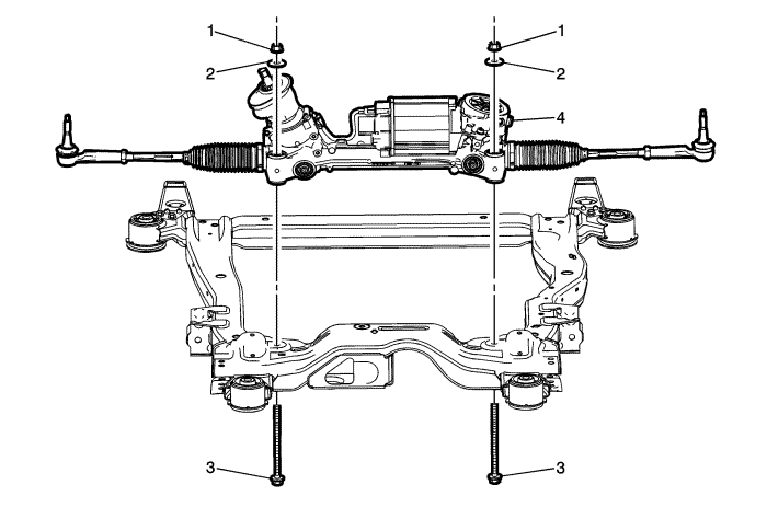
3
| Steering Gear Bolt (Qty: 2)
Warning: This component is equipped with torque-to-yield fasteners. Install a NEW torque-to-yield fastener when installing this component. Failure to replace the torque-to-yield fastener could cause bodily injury and damage to the vehicle or component.
Procedure
- Remove the 2 steering gear bolts.
Discard the bolts.
- Install 2 NEW steering gear bolts. Hold the steering gear nuts while tightening the steering gear bolts using the EN-45059 meter .
Tighten
- 110 N·m (81 lb ft)
- 160 degrees
Special ToolsEN-45059 Angle Meter
For equivalent regional tools, refer to Special Tools .
|