To the top of the document
Volt
   
GMDE Start Page Load static TOC Load dynamic TOC Help?

Drivetrain and Front Suspension Frame Replacement

Removal Procedure

  1. Disable the high voltage system. Refer to High Voltage Disabling .
  2. Caution: With wheels of the vehicle facing straight ahead, secure the steering wheel utilizing steering column anti-rotation pin, steering column lock, or a strap to prevent rotation. Locking of the steering column will prevent damage and a possible malfunction of the SIR system. The steering wheel must be secured in position before disconnecting the following components:

       • The steering column
       • The intermediate shaft(s)
       • The steering gear
    After disconnecting these components, do not rotate the steering wheel or move the front tyres and wheels. Failure to follow this procedure may cause the SIR coil assembly to become un-centred and cause possible damage to the SIR coil. If you think the SIR coil has became uncentred, refer to your specific SIR coil's centring procedure to re-centre SIR Coil.

  3. Remove the front bumper fascia. Refer to Front Bumper Fascia Removal and Installation : Volt → Ampera .
  4. Support the radiator and condenser from above using the condenser tabs on each side.
  5. Install the engine support fixture. Refer to Engine Support Fixture .
  6. Remove the lower steering intermediate shaft bolt. Refer to Intermediate Steering Shaft Replacement .
  7. Raise the vehicle on a hoist. Refer to Lifting and Jacking the Vehicle .
  8. Remove the catalytic converter. Refer to Catalytic Converter Replacement .

  9. 2028081
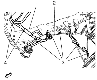
  10. Remove the wheel speed sensor wiring harness (2) from the frame on both sides.
  11. Remove the wiring harness retainers (3) from the frame and the lower control arm.

  12. Remove the heater inlet and outlet pipe bolts from frame. Refer to Heater Inlet And Outlet Pipe Replacement .
  13. Position the heater water auxiliary pump and support to the side. Refer to Heater Water Auxiliary Pump Replacement .
  14. Caution: Electrostatic discharge (ESD) can damage many solid-state electrical components. ESD susceptible components may or may not be labelled with the ESD symbol. Handle all electrical components carefully. Use the following precautions in order to avoid ESD damage:

       • Touch a metal ground point in order to remove your body's static charge before servicing any electronic component; especially after sliding across the vehicle seat.
       • Do not touch exposed terminals. Terminals may connect to circuits susceptible the ESD damage.
       • Do not allow tools to contact exposed terminals when servicing connectors.
       • Do not remove components from their protective packaging until required to do so.
       • Avoid the following actions unless required by the diagnostic procedure:
          - Jumpering or grounding of the components or connectors.
          - Connecting test equipment probes to components or connectors. Connect the earth lead first when using test probes.
       • Ground the protective packaging of any component before opening. Do not rest solid-state components on metal workbenches, or on top of TVs, radios, or other electrical devices.

  15. Disconnect the electrical connectors from the electronic power steering assembly. Refer to FEP Connectors : Steering Gear .
  16. Remove the wire harness bracket and bolt from the power steering gear.
  17. Remove the lower ball joints from the steering knuckles. Refer to Steering Knuckle Replacement .
  18. Remove the stabiliser link nut from the strut, then discard the nut. Refer to Stabilizer Shaft Link Replacement .
  19. Remove the outer track rods and track rod nuts from the steering knuckles. Refer to Steering Linkage Outer Track rod Replacement .
  20. Remove the rear transmission mount to rear transmission mount bracket through bolt. Refer to Transmission Rear Mount Replacement .
  21. Lower the vehicle until the drivetrain and front suspension frame contacts the engine support table.

  22. 2188954
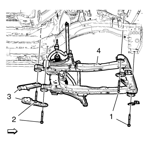
  23. Remove the frame front bolts (1).
  24. Remove the frame rear bolts (2).
  25. Remove the frame reinforcements (3).
  26. Remove the frame (4) from the vehicle.
  27. Remove the following components if replacing the frame:
  28. • The lower control arms--Refer to Lower Control Arm Replacement .
    • The stabilizer shaft--Refer to Stabilizer Shaft Replacement .
    • The radiator support brackets
    • The steering gear--Refer to Steering Gear Replacement .
    • The rear transmission mount--Refer to Transmission Rear Mount Replacement .

Installation Procedure

    Caution : Refer to Fastener Caution in the Preface section.

  1. Install the following components on the drivetrain and front suspension frame, if removed:
  2. • The rear transmission mount--Refer to Transmission Rear Mount Replacement .
    • The radiator support brackets--Tighten the fasteners to 22 N·m (16 lb ft).
    • The stabilizer shaft--Refer to Stabilizer Shaft Replacement .
    • The lower control arms--Refer to Lower Control Arm Replacement .
    • The steering gear--Refer to Steering Gear Replacement .
  3. Install the frame to the vehicle.
  4. Install the frame rear bolts (2) and tighten to 160 N·m (118 lb ft).
  5. Install the frame front bolts (1) and tighten to 160 N·m (118 lb ft).
  6. Install the frame reinforcements (3) and tighten to 58 N·m (43 lb ft).
  7. Install the rear transmission mount to rear transmission mount bracket through bolt. Refer to Transmission Rear Mount Replacement .
  8. Install the outer track rods and track rod nuts to the steering knuckles. Refer to Steering Linkage Outer Track rod Replacement .
  9. Caution: Electrostatic discharge (ESD) can damage many solid-state electrical components. ESD susceptible components may or may not be labelled with the ESD symbol. Handle all electrical components carefully. Use the following precautions in order to avoid ESD damage:

       • Touch a metal ground point in order to remove your body's static charge before servicing any electronic component; especially after sliding across the vehicle seat.
       • Do not touch exposed terminals. Terminals may connect to circuits susceptible the ESD damage.
       • Do not allow tools to contact exposed terminals when servicing connectors.
       • Do not remove components from their protective packaging until required to do so.
       • Avoid the following actions unless required by the diagnostic procedure:
          - Jumpering or grounding of the components or connectors.
          - Connecting test equipment probes to components or connectors. Connect the earth lead first when using test probes.
       • Ground the protective packaging of any component before opening. Do not rest solid-state components on metal workbenches, or on top of TVs, radios, or other electrical devices.

  10. Install the wire harness bracket to the power steering gear. Tighten the wire harness bracket bolts to 9 N·m (80 lb in).
  11. Connect the electrical connectors to the electronic power steering assembly. Refer to FEP Connectors : Steering Gear .

  12. 2028083
  13. Install the stabiliser shaft link. Tighten the steering linkage tie rod nut stabiliser shaft link nuts to 65 N·m (48 lb ft).
  14. Install the lower ball joints to the steering knuckles. Refer to Steering Knuckle Replacement .

  15. 2028081
  16. Install the wheel speed sensor wiring harness (2) to the frame on both sides.
  17. Install the wiring harness retainers (3) to the frame and the lower control arm.

  18. Install the heater water auxiliary pump and support to the frame. Refer to Heater Water Auxiliary Pump Replacement .
  19. Install the heater inlet and outlet pipe fasteners to the frame. Refer to Heater Inlet And Outlet Pipe Replacement .
  20. Install the catalytic converter. Refer to Catalytic Converter Replacement .
  21. Lower the vehicle.
  22. Remove the support of the radiator and condenser.
  23. Install the lower steering intermediate shaft. Refer to Intermediate Steering Shaft Replacement .
  24. Remove the engine support fixture from the vehicle.
  25. Install the front bumper fascia. Refer to Front Bumper Fascia Removal and Installation : Volt → Ampera .
  26. Check the wheel alignment. Refer to Wheel Alignment Measurement .
  27. Enable the high voltage system. Refer to High Voltage Enabling .


&#169© Copyright Chevrolet. All rights reserved