Danger: Do not use a service jack in locations other than those specified to lift this vehicle. Lifting the vehicle with a jack in those other locations could cause the vehicle to slip off the jack and roll; this could cause injury or death.
- Place the vehicle on a hoist. Refer to Lifting and Jacking the Vehicle .
Danger: Always perform the High Voltage Disabling procedure prior to servicing any High Voltage component or connection. Personal Protection Equipment (PPE) and proper procedures must be followed.
The High Voltage Disabling procedure will perform the following tasks:
| • | Identify how to disable high voltage. |
| • | Identify how to test for the presence of high voltage. |
| • | Identify condition under which high voltage is always present and personal protection equipment (PPE) and proper procedures must be followed. |
- Disable the high voltage system. Refer to High Voltage Disabling .
- Remove the air cleaner resonator outlet duct. Refer to Air Cleaner Resonator Outlet Duct Replacement .
- Remove the drive motor generator power inverter module. Refer to Drive Motor Generator Power Inverter Module Replacement .
- Remove the front bumper fascia. Refer to
Front Bumper Fascia Removal and Installation : Volt → Ampera .
- Using mechanic's wire, secure the radiator assembly to the radiator core support.
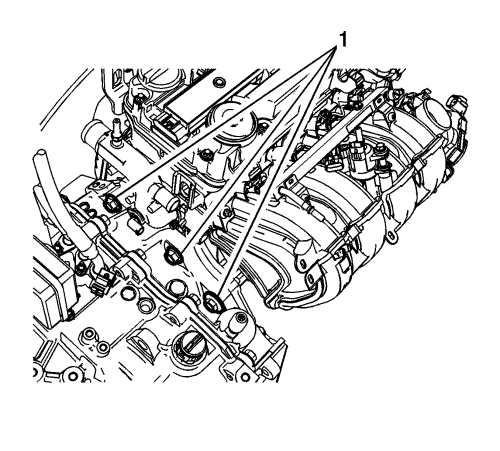
- Remove the three upper bell housing fasteners (1).
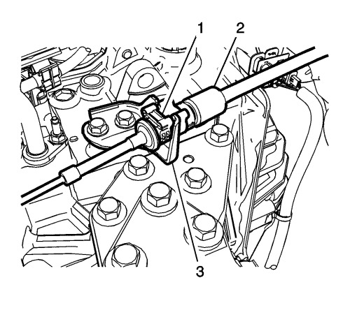
- Press the locking tab (1) rearward in order to release the transmission range selector lever cable (2) from the cable bracket.
- Disconnect the transmission range selector lever cable terminal (1) from the transmission manual pin, then position the cable out of the way.
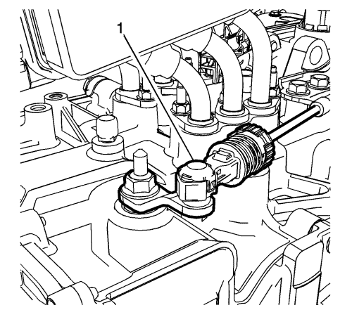
- Remove the shift control cable bracket fasteners (1), then the bracket (2) from the transmission.
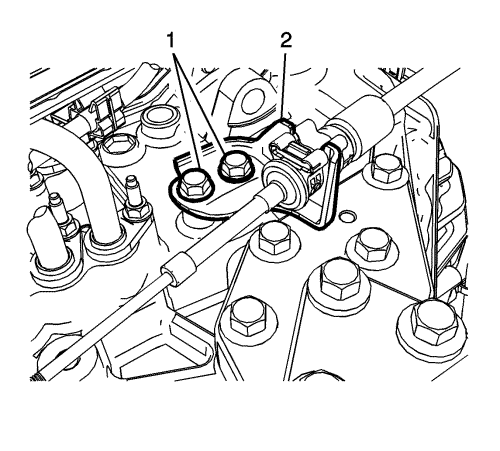
Warning: Hold the transmission range selector lever while removing or installing the lever retaining nut. Failure to hold the lever can cause damage to the transmission internal park system components which could allow the vehicle to roll when placed in the park position.
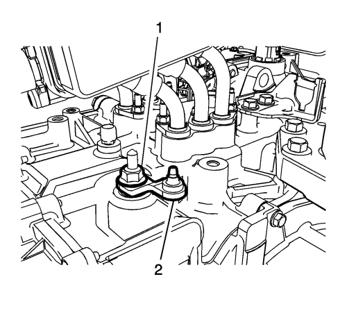
- Remove the transmission range selector lever nut (1).
- Remove the transmission range selector lever (2).
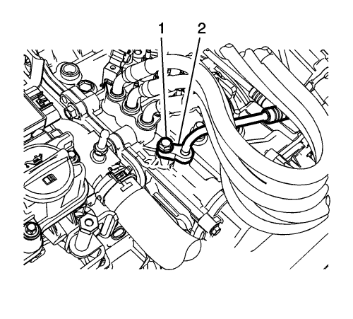
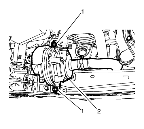
- Remove the transmission fluid cooler inlet pipe fastener (1), then disconnect the inlet pipe (2) from the transmission.
- Inside the passenger compartment, disconnect the intermediate steering shaft from the steering gear. Refer to Intermediate Steering Shaft Replacement .
Danger: Do not use a service jack in locations other than those specified to lift this vehicle. Lifting the vehicle with a jack in those other locations could cause the vehicle to slip off the jack and roll; this could cause injury or death.
- Raise and support the vehicle. Refer to Lifting and Jacking the Vehicle .
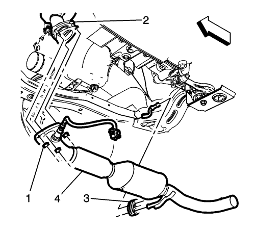
- Remove the catalytic converter assembly (4) from the vehicle. Refer to Catalytic Converter Replacement .
- Drain the transmission fluid. Refer to Transmission Fluid Replacement .
- Remove the heater inlet and outlet pipe to frame fasteners (1).
- Remove the front wheelhouse liners. Refer to Front Wheelhouse Front Liner Replacement .

- Remove the stabiliser link nuts (1) from the two front stabiliser links.
- Disconnect the stabiliser links from the strut assemblies.
- Disconnect the outer tie rod ends from the steering knuckles. Refer to Steering Linkage Outer Track rod Replacement .
Note: Do Not disconnect the brake hoses from the callipers.
- Remove the front brake callipers from the calliper brackets, then suspend the callipers with mechanic's wire to the body.
- Disconnect the front steering knuckles from the strut assemblies. Refer to Steering Knuckle Replacement .
- Remove the heater water auxiliary pump fasteners (1), then position the pump out of the way.
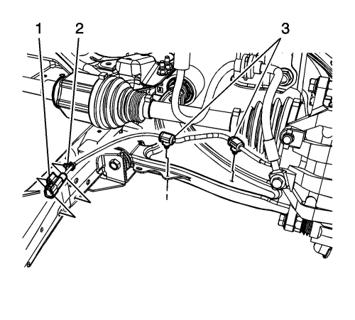
- Disconnect the front left and right wheel speed sensor connectors (1).
- Disconnect the left wheel drive shaft from the transmission, then suspend the wheel drive shaft with mechanic's wire.
- Disconnect the right wheel drive shaft from the front wheel drive intermediate shaft, then suspend the wheel drive shaft with mechanic's wire.
- Disconnect the rear transmission mount from the rear transmission bracket.
- Remove the rear transmission mount bracket from the transmission. Refer to Transmission Mount Bracket Replacement - Rear .
- Remove the front wheel drive intermediate shaft. Refer to Front Wheel Drive Intermediate Shaft Replacement .
- Lower the vehicle.
- Install the engine support fixture. Refer to Engine Support Fixture .
- Remove the transmission mount side bracket. Refer to Transmission Mount Transmission-Side Bracket Replacement .
- Disconnect the transmission fluid cooler outlet pipe from the transmission. Refer to Transmission Fluid Cooler Outlet Pipe Replacement .
- Using suitable chains or straps, secure the front of the vehicle to the hoist arms.
- Disconnect the wiring harnesses from the drivetrain and front suspension frame as necessary.
- Remove the drive motor battery coolant cooler inlet and outlet hose clip retainer bolt. Refer to Drive Motor Battery Coolant Inlet Hose Replacement .
- Using a suitable engine support table or equivalent, lower the vehicle until the drivetrain and front suspension frame contacts the engine support table.
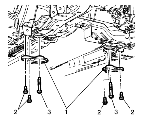
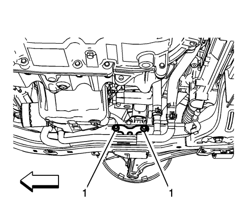
- Remove the drivetrain and front suspension frame reinforcements (1) from the rear of the frame.
- Remove the front drivetrain and front suspension retaining bolts.
Note: Slightly raise the vehicle, Do Not raise the vehicle too far or damage to Electrical Power Steering (EPS) wiring harness could occur.
- Slightly raise the vehicle off of the frame to gain access to the EPS connectors.
- Disconnect the EPS electrical connectors from the power steering gear assembly. Refer to
FEP Connectors : Steering Gear .
- Raise the vehicle off the drivetrain and front suspension frame.
- Position a suitable transmission jack under the transmission.
Warning: Handle with care, the transmission assembly weighs over 90.7 kg (200 lbs). Bodily injury could occur if not handled properly.
- Using a suitable straps or chains, secure the transmission to the transmission jack.
- Disconnect the transmission electrical connectors from the transmission, then position the wiring harnesses out of the way.
- Disconnect the ground strap from the rear of the transmission.
- Remove the starter opening cover located below the intake manifold.
- Remove the four torque damper to flywheel bolts.
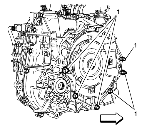
- Remove the six lower transmission to engine fasteners (1).
- Remove the transmission to engine stud.
- Lower the transmission assembly from the vehicle.


