MAINTENANCE AND REPAIR
ON-VEHICLE SERVICE
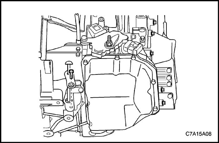


Transaxle Fluid Level Checking Procedure
- Park the vehicle on a flat level surface.
- Operate the vehicle in order for the transaxle fluid temperature to reach the normal operating range.
Notice : Transaxle normal temperature: 70-80 °C (158-176 °F)
- With the engine at idle, manual shift through all transaxle ranges and return to the PARK position. Leave the engine idling.
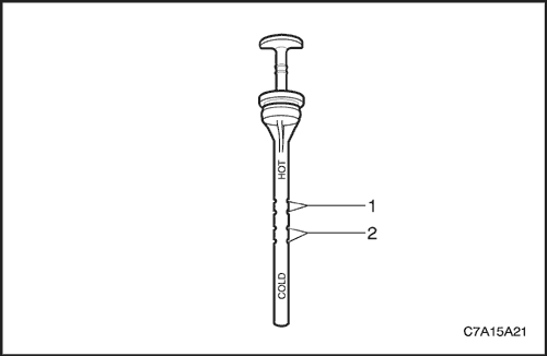


- Remove the transaxle fluid level indicator bolt.
- Remove the transaxle fluid level indicator.
- Wipe away any transaxle fluid from the indicator.
- Insert the indicator into the transaxle until fully seated.
Important : Inspecting transaxle fluid level when not at normal temperature can give an incorrect measurement. The transaxle fluid expands when warm.
- Remove the indicator and inspect the level and the condition of the fluid on the indicator:
- Transaxle fluid level at normal operating temperature (1).
- Transaxle fluid level if cold (2).
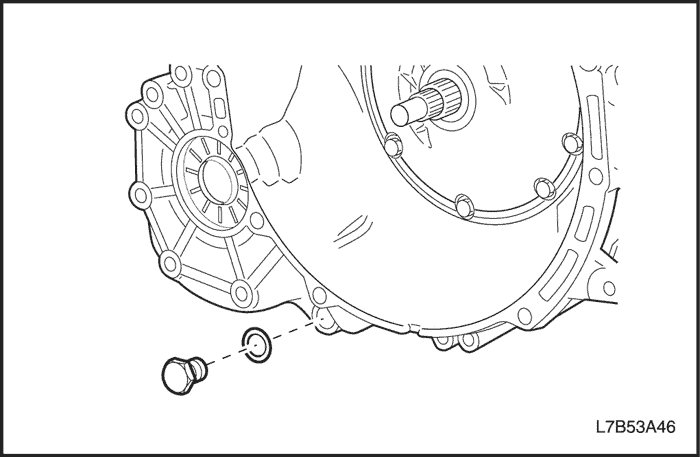


- If the fluid level is incorrect, inspect for the following conditions:
- Fluid below level, inspect for a leak and add the fluid through the fluid level indicator location.
- Fluid above level, transaxle is overfilled.
- Drain some of the fluid through the drain plug. Check the fluid level.
Important : When adding the fluid or making a complete fluid change, always use ESSO JWS 3309 US ATF.


- Install the fluid level indicator and bolt.
Tighten
Tighten the fluid level indicator bolt to 10 N•m (89 lb-in).


Transaxle Fluid Replacement
Removal Procedure
- Raise and support the vehicle.
- Remove the drain plug and drain fluid. Allow at least 5 minutes for the fluid to drain completely.
- Remove the gasket from the drain plug and discard.


Installation Procedure
- Install the new gasket on the drain plug.
- Install the drain plug.
Tighten
Tighten the drain plug to 40 N•m (30 lb-ft).
- Make sure vehicle is level.


- Remove the fluid level indicator bolt and indicator.
Important : Always use ESSO JWS 3309 US ATF.
Important : Do not remove the anchor bolt located on top of the transaxle for checking fluid or adding fluid. Removing the bolt will dislocate internal components and require the transaxle to be removed from the vehicle and disassembled for repair.
- Add the transaxle fluid to the transaxle, using the fluid level indicator location.
- Start engine and operate vehicle until transaxle fluid temperature reaches 70-80 °C (158-176 °F).


- Apply parking brake.
- Depress brake pedal and move shift lever slowly through all gear ranges from park (P) to low range, pausing for about 3 seconds in each range. Return the shift lever to park (P) range at idle condition.
- Pull level gauge out again and check if fluid level is within the HOT range.
- Install the fluid level indicator.
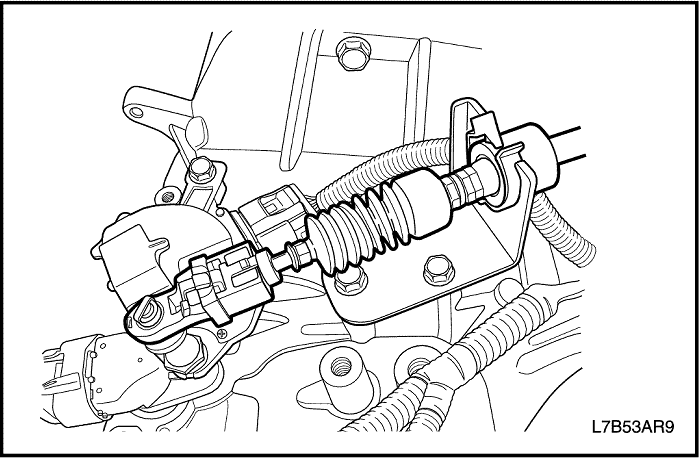


Shift Control Cable Adjustment
Adjustment Procedure
- Move the shift control lever into the N - Neutral position.
Important : The shift control cable must be disconnected from the transmission range switch lever prior to disconnecting it from the control cable bracket. Otherwise damage to the manual shift shaft may result, requiring transaxle disassembly.
- Disconnect the shift control cable from the TR switch lever.
- Disconnect the shift control cable from the control cable bracket by depressing the control cable retainer clip tabs and pulling up. Discard the clip.
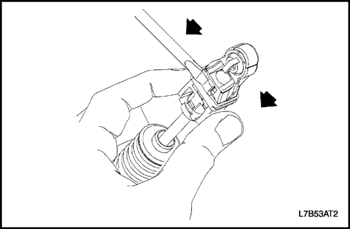


- Release the shift control cable assembly adjustment lock.
- Slide the black tab back.
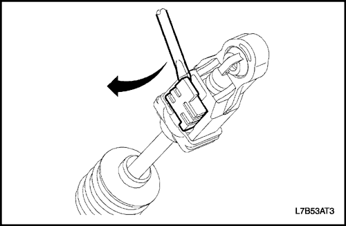


- Insert a screwdriver into the slot under the white tab and pull up on the white tab.


- Install the shift control cable into the shift control cable bracket. Secure with a new shift control cable retainer clip. An audible snap will be heard when properly installed.
- With the TR switch lever in neutral(N), snap the cable end fitting onto the ball stud of the TR switch lever. An audible snap will be heard when properly installed.
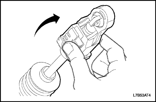


- Lock the control cable adjustment tab.
- Push down on the white tab to secure in place.
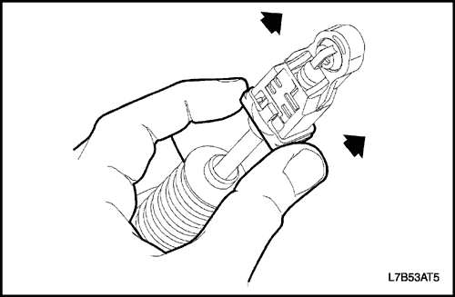


- Slide the black tab over the white tab to lock in place.
- Verify the proper operation.


Shift Control Cable
Removal Procedure
- Disconnect the negative battery cable.
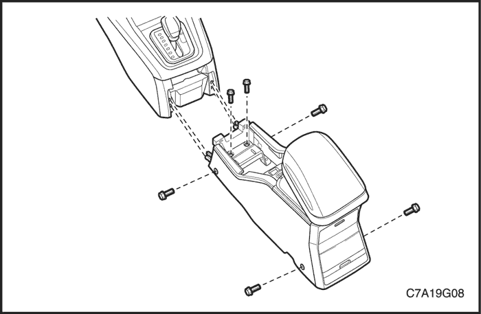
- Remove the floor console. Refer to Section 9G, Interior Trim.
- Apply the parking brake.
- Place the shift control lever into N position.
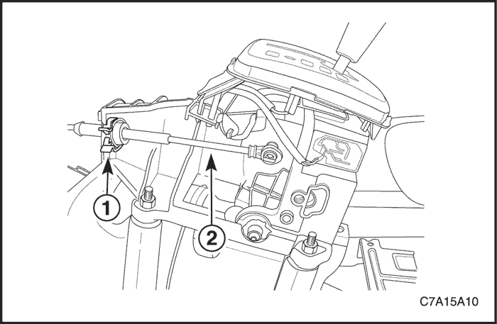


- Remove the shift control cable retaining clip (1) and cable (2) from the shift control lever assembly.


Important : The shift control cable must be disconnected from the transmission range switch lever prior to disconnecting it from the control cable bracket. Otherwise damage to the manual shift shaft may result, requiring transaxle disassembly.
- Disconnect the shift control cable from the TR switch lever.
- Disconnect the shift control cable from the control cable bracket by depressing the control cable retainer clip tabs and pulling up. Discard the clip.
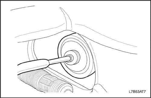


- Remove the shift control cable from the dash panel.
- Remove the shift control cable from the vehicle.


Installation Procedure
- Route the shift control cable through the cable bracket.
- Secure the cable to the bracket with a new control cable retaining clip. An audible snap will be heard when properly installed.
- With the TR switch lever in neutral(N), install the shift control cable end fitting onto the ball stud of the TR switch lever. An audible snap will be heard when the cable is properly installed.


- Secure the shift control cable grommet by pressing the cable into the pass-thru hole in the dash panel.


- Ensure the shift control lever is in the neutral (N) position.
- Connect the shift control cable to the shift control lever assembly. Secure the cable with a new shift control cable retaining clip (1).
- Install the shift control cable onto the shift control lever.
- Adjust the shift control cable. Refer to "Shift Control Cable Adjustment" in this section.


- Install the front console. Refer to Section 9G, Interior Trim.
- Connect the negative battery cable.


Shift Control Lever Assembly
Removal Procedure
- Disconnect the negative battery cable.
- Remove the floor console. Refer to Section 9G, Interior Trim.
- Disconnect the electrical wiring connectors.
- Remove the shift control cable retaining clip (1) and shift control cable(2) from the shift control lever assembly.
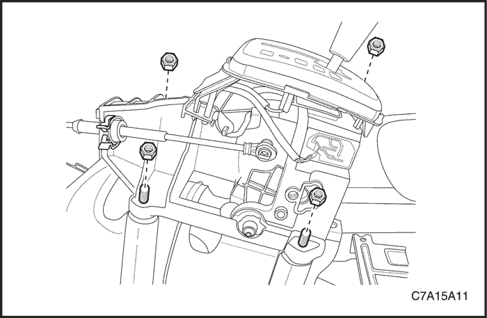


- Remove the shift control lever assembly mounting nuts and the shift control lever assembly.


Installation Procedure
- Install shift control lever assembly mounting nuts.
Tighten
Tighten the shift control lever assembly mounting nuts to 8 N•m (71 lb-in).


- Install the cable (2) onto the shift control lever assembly and secure the the cable with a new shift control cable retaining clip (1).
- Adjust the cable. Refer to "Shift Control Cable Adjustment" in this section.
- Connect the electrical wiring connectors.
- Install the floor console. Refer to Section 9G, Interior Trim.
- Connect the negative battery cable.
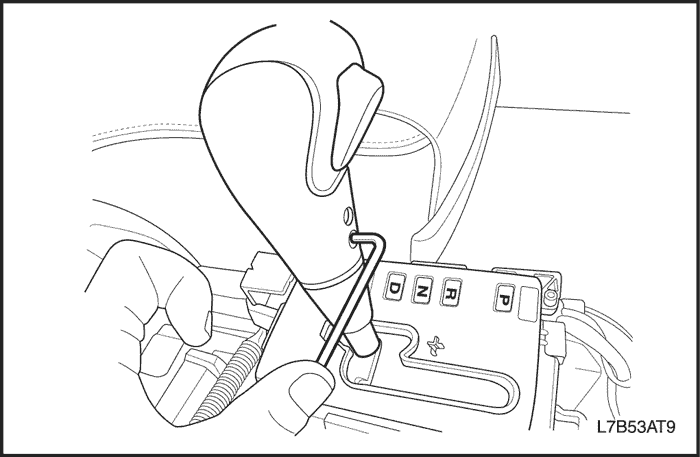


Shift Control Knob
Removal Procedure
- Apply the parking brake.
- Move the shift control lever rearward to one of the low gear position.
- Remove the two bolts.
- Remove the knob from the shift control lever.


Installation Procedure
- Install the knob and bolts to the shift control lever.
Tighten
Tighten the shift control knob bolts to 2 N•m (18 lb-in).
- Place the shift control lever in the PARK position.


Transmission Range (TR) Switch
Tools Required
J 45404 Transmission Indicator Alignment Tool
Removal Procedure
- Disconnect the negative battery cable.
- For HFV6 3.2L or 2.0S Diesel, remove the ECM bracket.
Important : The transaxle manual shaft must be in neutral (N) position prior to re-installing the switch.
- Apply the parking brake and place control shift lever in neutral (N).
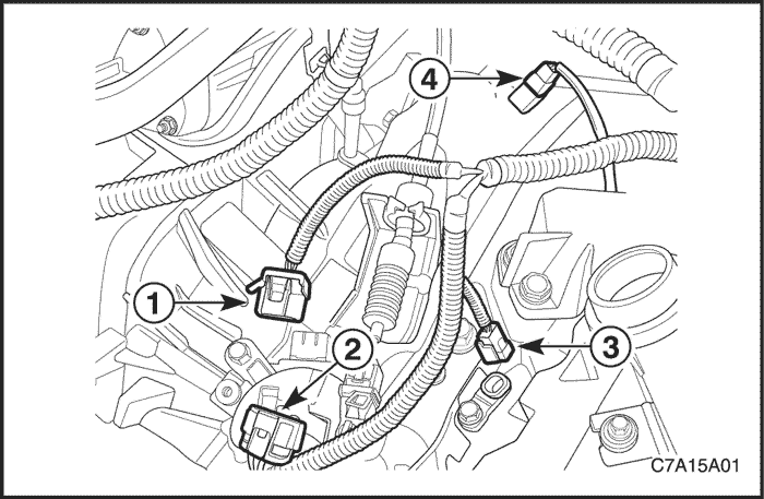
- Disconnect the TR switch electrical connector (1) and the transaxle electrical connector (2).


- Disconnect the cable from the TR switch lever. Refer to "Shift Control Cable" in this section.
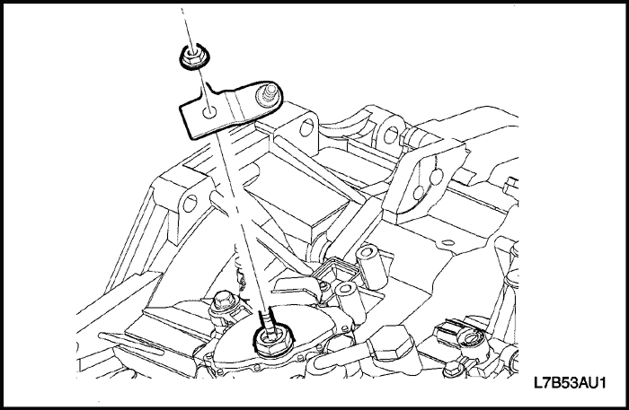


- Remove the TR switch lever nut and lever.
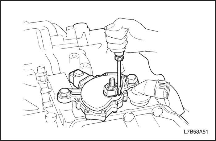


- Using a screwdriver, bend the lockwasher tabs down away from the manual shaft nut.
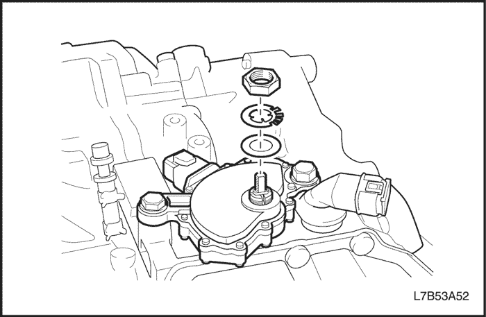


- Remove the nut, lock tab washer, and flat washer.
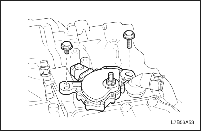


- Remove the TR switch bolts.
- Remove the TR Switch.


Installation Procedure
- Install the transmission range (TR) switch to the manual shaft lever.
- Install the bolts. Hand tighten ONLY at this time.


- Install the flat washer, lock tab washer, and nut.
Tighten
Tighten the TR switch nut to 7 N•m (62 lb-in).
- Ensure the manual shaft is in neutral (N) position.


- Bend the lock washer tabs up to secure the nut.
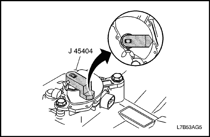


- Install the J 45404 to the manual shaft and rotate the TR switch until the neutral base line on the switch lines up with the indicator line on the J 45404.
- Tighten the TR switch bolts.
Tighten
Tighten the TR switch bolts to 25 N•m (18 lb-ft).
- Remove the J 45404 from the manual shaft.


- Install the TR switch lever and nut.
Tighten
Tighten the TR lever nut to 16 N•m (12 lb-ft).


- Install the cable to TR switch lever and adjust the cable. Refer to "Shift Control Cable" in this section.


- Connect the electrical connector (1,2).
- For HFV6 3.2L or 2.0S Diesel, install the ECM bracket.
- Connect the negative battery cable.
- After adjusting the TR switch, verify the engine only starts in park (P) or neutral (N). If the engine starts in any other position, readjust the switch.


Transmission Range (TR) Switch Adjustment
Tools Required
J 45404 Transmission Indicator Alignment Tool
Adjustment Procedure
- Disconnect the negative battery cable.
- For HFV6 3.2L or 2.0S Diesel, remove the ECM bracket.
- Shift the control lever into neutral (N) position.
- Remove the shift control cable from the TR switch lever.


- Loosen the TR switch bolts.


- Install the J 45404 to the manual shaft and rotate the TR switch until the neutral base line on the switch lines up with the indicator line on the J 45404.
- Tighten the TR switch bolts.
Tighten
Tighten the TR switch bolts to 25 N•m (18 lb-ft).
- Remove the J 45404 from the manual shaft.


- Install the shift control cable to the TR switch lever and adjust the cable. Refer to "Shift Control Cable" in this section.
- For HFV6 3.2L or 2.0S Diesel, install the ECM bracket.
- Connect the negative battery cable.
- After adjusting the transaxle range switch, verify the engine only starts in park (P) or neutral (N). If the engine starts in any other position, readjust the switch.


Input Speed Sensor
Removal Procedure
- Disconnect the negative battery cable.
- For HFV6 3.2L or 2.0S Diesel, remove the ECM bracket.
- Remove the input speed sensor electrical connector (3) from the input speed sensor.
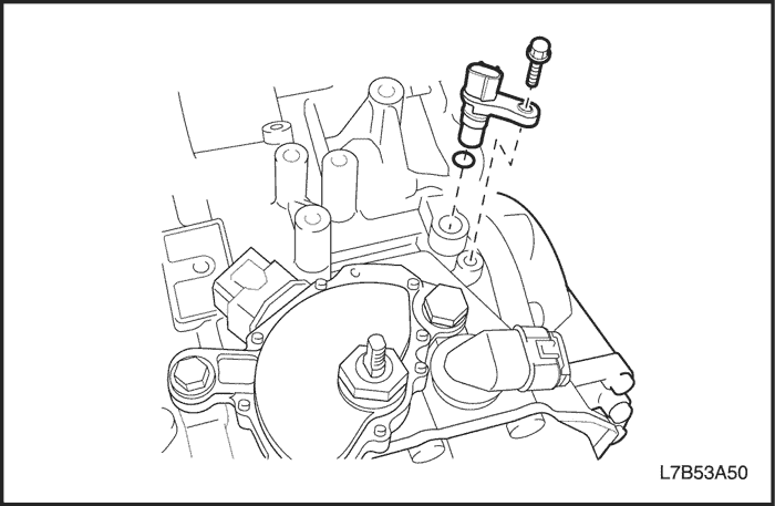


- Remove the input speed sensor bolt.
- Remove the input speed sensor from the transaxle.
- Remove the input speed sensor O-ring. Discard the O-ring.


Installation Procedure
- Apply the transaxle fluid to the new input speed sensor O-ring.
- Install the new input speed sensor O-ring onto the input speed sensor.
- Install the input speed sensor to the transaxle.
- Install the input speed sensor bolt.
Tighten
Tighten the input speed sensor bolt to 6 N•m (53 lb-in).


- Connect the electrical connector (3) to the input speed sensor.
- For HFV6 3.2L or 2.0S Diesel, install the ECM bracket.
- Connect the negative battery cable.


Output Speed Sensor
Removal Procedure
- Disconnect the negative battery cable.
- For HFV6 3.2L or 2.0S Diesel, remove the ECM bracket.
- Remove the output speed sensor electrical connector (4) from the output speed sensor.
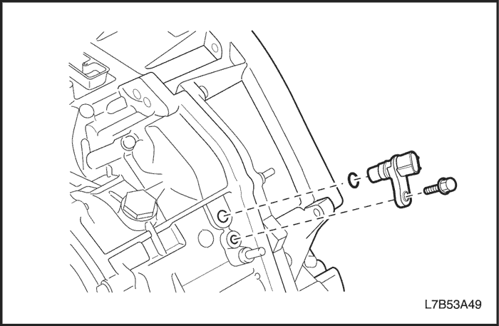


- Remove the output speed sensor bolt.
- Remove the output speed sensor from the transaxle.
- Remove the output speed sensor O-ring. Discard the O-ring.


Installation Procedure
- Apply the transaxle fluid to the new output speed sensor O-ring.
- Install the new output speed sensor O-ring onto the input speed sensor.
- Install the output speed sensor to the transaxle.
- Install the output speed sensor bolt.
Tighten
Tighten the output speed sensor bolt to 6 N•m (53 lb-in).


- Connect the electrical connector (4) to the output speed sensor.
- For HFV6 3.2L or 2.0S Diesel, install the ECM bracket.
- Connect the negative battery cable.
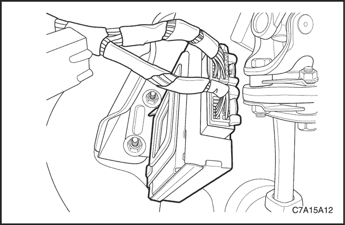


Transmission Control Module (TCM)
Removal Procedure
- Disconnect the negative battery cable.
- Disconnect the TCM wiring connectors.
- Remove the transmission control module (TCM) and nuts.


Installation Procedure
- Install the TCM retaining nuts.
Tighten
Tighten the TCM retaining nuts to 20 N•m (15 lb-ft).
- Connect the electrical connectors.
- Connect the negative battery cable.


Oil Cooler Line Assembly
Removal Procedure
- Raise and suitably support the vehicle.
- Place a drain pan or suitable container under the vehicle.
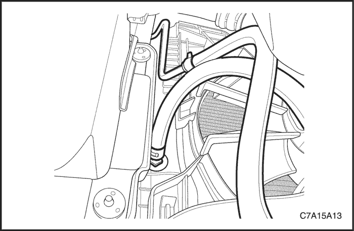
- Disconnect the oil cooler lines from the radiator.
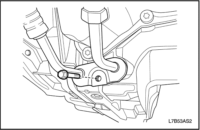


- Remove the oil cooler line assembly bolt from the transaxle.
- Remove the oil cooler line assembly.
- Replace the transaxle oil cooler line seals. Refer to "Oil Cooler Line Seals" in this section.


Installation Procedure
- Install the oil cooler line assembly to the transaxle.
- Install the oil cooler line assembly bolt.
Tighten
Tighten the oil cooler line assembly bolt to 10 N•m (89 lb-in).


- Connect the oil cooler lines to the radiator.
- Lower the vehicle
- Add fluid to the transaxle.
- Check the fluid level. Refer to "Transaxle Fluid Checking Procedure"in this section.


Oil Cooler Line Seals
Tools Required
J 41239-1 Cooler Line Seal Installer
J 45201 Cooler Line Seal Remover
Removal Procedure
- Raise and suitably support the vehicle.
- Place a drain pan or suitable container under the vehicle.
- Remove the transaxle oil cooler line assembly from the transaxle. Refer to "Oil Cooler Line Assembly" in this section.
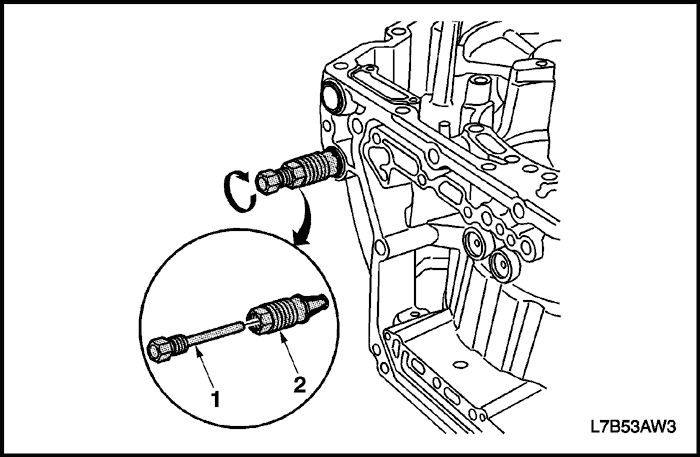


Important : Ensure that the J 45201 is fully seated into the transaxle seal bore.
- Insert the collet piece (2) of the J 45201 into the cooler line seal.
- Insert the forcing screw piece (1) of the J45201 into the collet (2).
- Tighten the forcing screw (1) until snug.
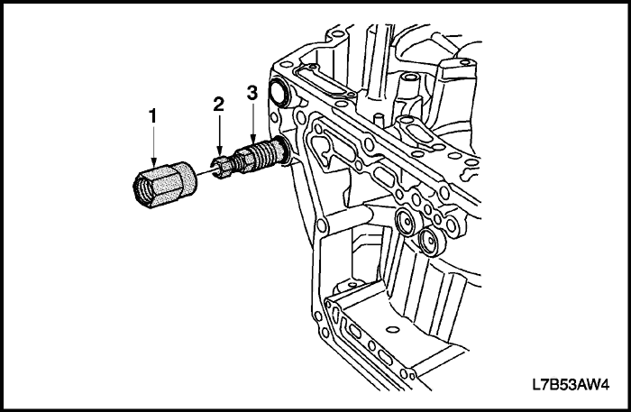


- Thread the collar piece (1) of the J 45201 onto the collet (3) until snug.
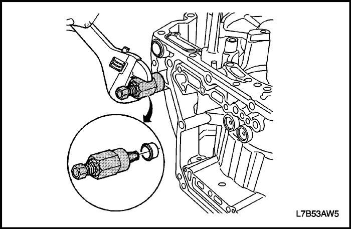


- Turn the collar clockwise in order to remove the cooler line seal.
- Discard the seal.
- Clean the case bores for the cooler line seals.


Installation Procedure
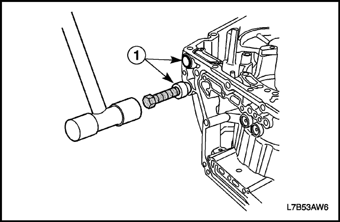
- Insert 2 new transaxle cooler line seals (1) into the case bore.
- Remove the nub from the J 41239-1.
- Install the nub of the J 41239-1 on the transaxle cooler line seals.
- Tap the 2 new transaxle cooler line seals (1) into the case bore.


- Install the oil cooler line assembly. Refer to "Oil Cooler Line Assembly"in this section.
- Lower the vehicle.
- Add fluid to the transaxle.
- Check the fluid level. Refer to "Transaxle Fluid Checking Procedure" in this section.
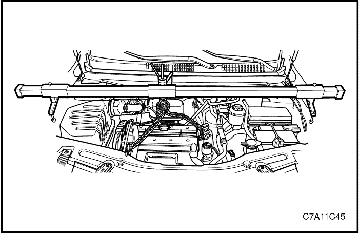


Left Transaxle Mounting Bracket
Tools Required
DW110-060 Engine Support Fixture
Removal Procedure
- Remove the battery and tray. Refer to Section 1E1, Engine Electrical - 2.0 Diesel ; Section 1E2, Engine Electrical - FAM II 2.4D ; Section 1E3, Engine Electrical - HFV6 3.2L.
- Install the DW110-060.
- Support the transaxle with a supporting jack.
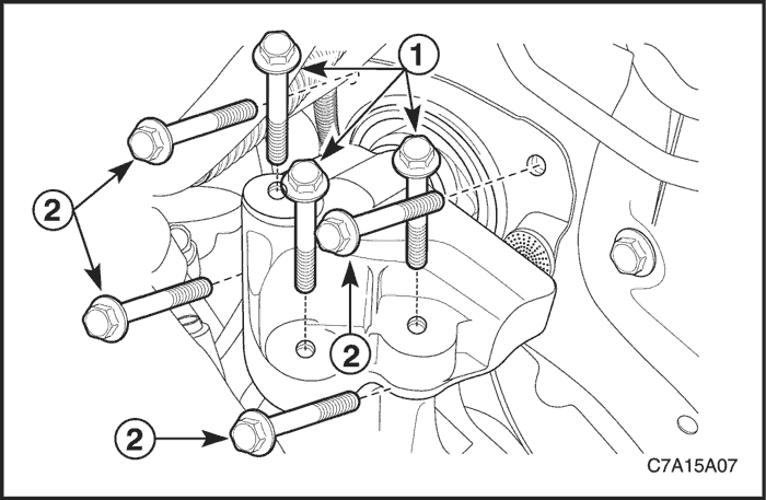


- Remove the left three transaxle mount bracket bolts (1).
- Remove the transaxle mount bolts (2).
- Remove the left transaxle mounting bracket.


Installation Procedure
- Install the transaxle mount bolts (2).
Tighten
Tighten the transaxle mount bolts (2) to 37 N•m (27 lb-ft).
- Install the left transaxle mounting bracket and three transaxle mounting bracket bolts (1).
Tighten
Tighten the left three transaxle mounting bracket bolts (1) to 50 N•m (37 lb-ft).


- Remove the DW110-060.
- Install the battery and tray. Refer to Section 1E1, Engine Electrical - 2.0 Diesel ; Section 1E2, Engine Electrical - FAM II 2.4D ; Section 1E3, Engine Electrical - HFV6 3.2L.


Transaxle Assembly
Tools Required
DW110-060 Engine Support Fixture
Removal Procedure
- Remove the battery and tray. Refer to Section 1E1, Engine Electrical - 2.0 Diesel ; Section 1E2, Engine Electrical - FAM II 2.4D ; Section 1E3, Engine Electrical - HFV6 3.2L.
- Drain the transaxle fluid. Refer to "Transaxle Fluid Replacement" in this section.
- Remove the power steering oil reservoir mounting bolts and put the reservoir aside.


- Disconnect the shift control cable from the transaxle. Refer to "Shift Control Cable" in this section.


- Disconnect the transmission range (TR) switch electrical connector (1).
- Disconnect the transaxle wiring electrical connector (2).
- Disconnect the input speed sensor electrical connector (3) and the output speed sensor electrical connector (4).
- Separate the interfered wiring harness near the transaxle.
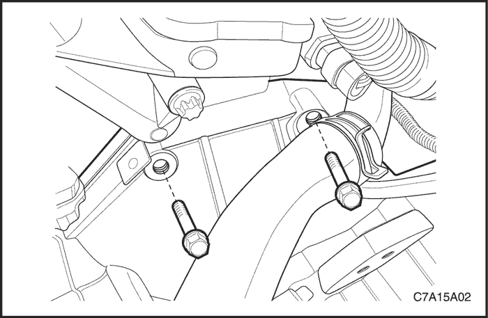


- Remove the upper two transaxle-to-engine bolts.


- Install the DW110-060.
- Raise and suitably support the vehicle.
- Remove the engine under covers. Refer to Section 9N, Frame and Underbody.
- Remove the left side dust cover.
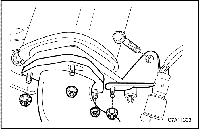


- Remove the exhaust front pipe. Refer to Section 1G1, Engine Exhaust - 2.0 Diesel ; Section 1G2, Engine Exhaust - FAM II 2.4D ; Section 1G3, Engine Exhaust - HFV6 3.2L.
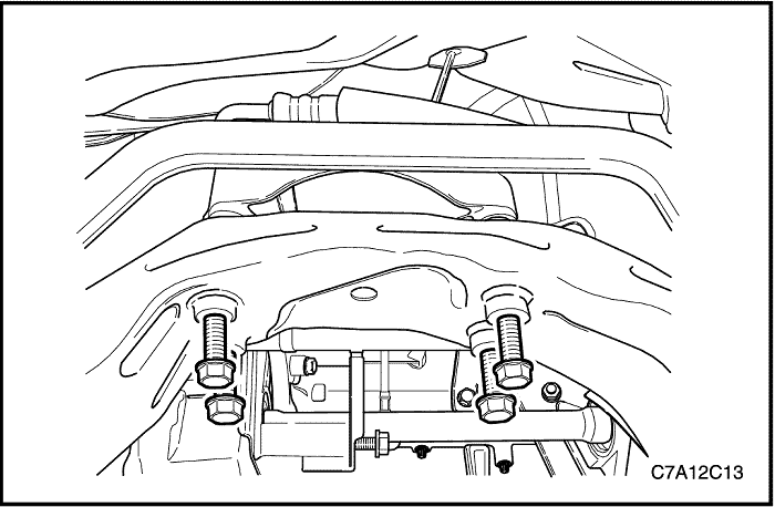


- Carefully remove the cradle from the vehicle. Refer to Section 2C, Front Suspension.
- Remove the drive axle. Refer to Section 3A, Front Drive Axle.
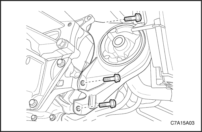


- Remove the front damper bush mounting bolts and the front damper bush.
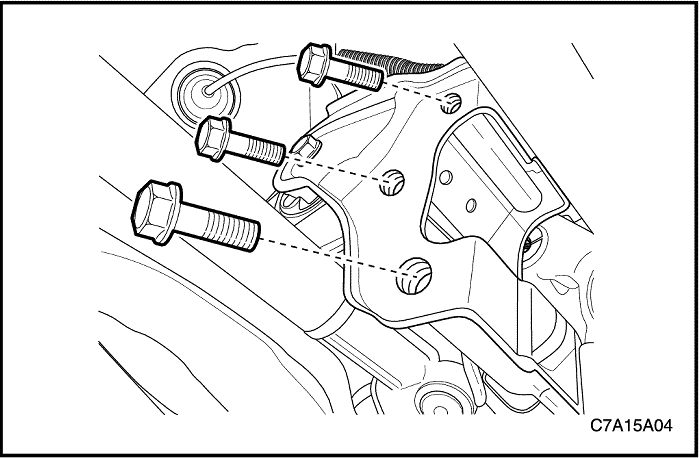


- Remove the rear transaxle mounting bracket bolts.
- Remove the rear damper bush and rear transaxle mounting bracket.
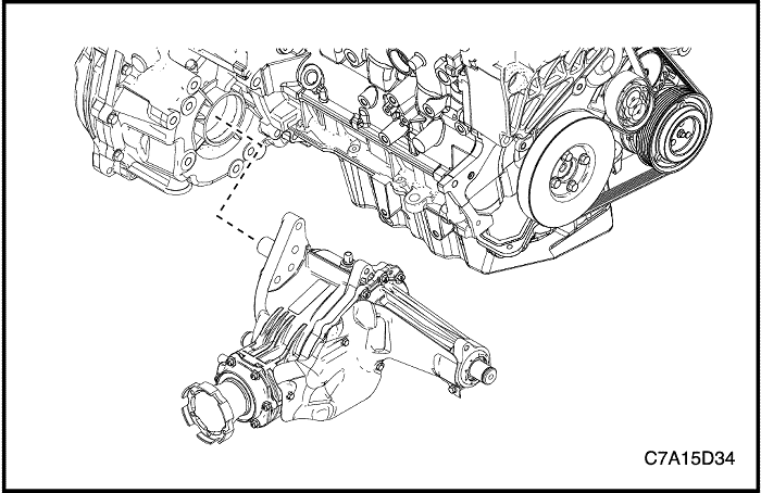


- For AWD, remove the transfer case from the transaxle. Refer to Section 5D, Transfer Case.
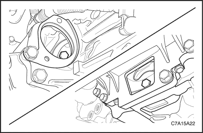


- Remove the starter. Refer to Section 1E1, Engine Electrical - 2.0 Diesel ; Section 1E2, Engine Electrical - FAM II 2.4D ; Section 1E3, Engine Electrical - HFV6 3.2L.
- Remove the six flywheel-to-torque converter bolts. For 2.0S Diesel, remove the plastic cover, then remove the six flywheel-to-torque converter bolts.


- Remove the oil cooler line from the transaxle. Refer to "Oil Cooler Line Assembly" in this section.
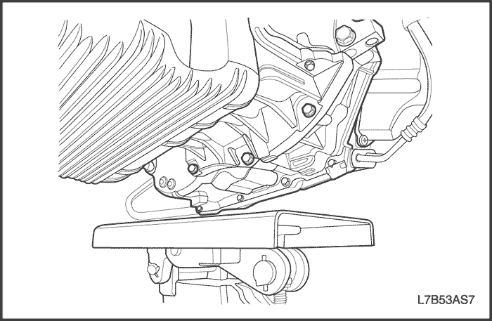


- Support the transaxle assembly using the supporting jack.
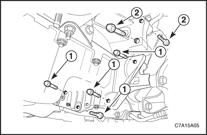


- Remove the oil pan flange-to-transaxle bolts (1).
- Remove the right lower engine-to-transaxle bolts (2) near the front damper bush.
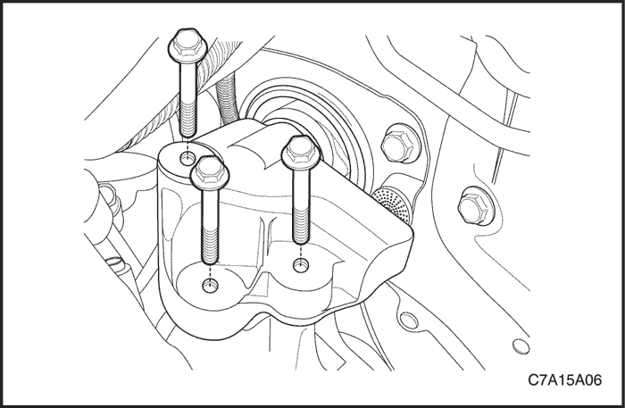


- Remove the left transaxle mounting bracket bolts. Refer to "Left Transaxle Mounting Bracket" in this section.


- Carefully remove the transaxle assembly from the vehicle.


Installation Procedure
- Install the transaxle into the vehicle and support the transaxle assembly using the supporting jack.


- Install the left transaxle mounting bracket bolts. Refer to "Left Transaxle Mounting Bracket" in this section.


- Install the right lower engine-to-transaxle bolts (2) near the front damper bush.
Tighten
Tighten the right lower engine-to-transaxle bolts (2) to 75 N•m (55 lb-ft).
- Install the oil pan flange-to-transaxle bolts (1).
Tighten
Tighten the oil pan flange-to-transaxle bolts (1) to 50 N•m (37 lb-ft).


- Install the oil cooler line to the transaxle. Refer to "Oil Cooler Line Assembly" in this section.


- Install the six flywheel-to-torque converter bolts. For 2.0S Diesel, tighten the bolts, then install the plastic cover.
Tighten
Tighten the flywheel-to-torque converter bolts to 45 N•m (33 lb-ft).
- Install the starter. Refer to Section 1E1, Engine Electrical - 2.0 Diesel ; Section 1E2, Engine Electrical - FAM II 2.4D ; Section 1E3, Engine Electrical - HFV6 3.2L.


- For AWD, install the transfer case into the transaxle. Refer to Section 5D, Transfer Case.


- Install the rear damper bush and rear transaxle mounting bracket.
- Install the rear transaxle mounting bracket bolts.
Tighten
Tighten the rear transaxle mounting bracket bolts to 90 N•m (66 lb-ft).


- Install the front damper bush and the front damper bush mounting bolts.
Tighten
Tighten the front damper bush mounting bolts to 50 N•m (37 lb-ft).


- Install the drive axle. Refer to Section 3A, Front Drive Axle.
- Carefully install the cradle from the vehicle. Refer to Section 2C, Front Suspension.


- Install the exhaust front pipe. Refer to Section 1G1, Engine Exhaust - 2.0 Diesel ; Section 1G2, Engine Exhaust - FAM II 2.4D ; Section 1G3, Engine Exhaust - HFV6 3.2L.
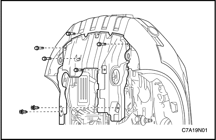


- Install the left side dust cover.
- Install the engine under covers. Refer to Section 9N, Frame and Underbody.
- Lower the vehicle.


- Install the upper transaxle-to-engine bolts.
Tighten
For FAM II 2.4D or 2.0S Diesel, tighten the upper transaxle-to-engine bolts to 75 N•m (55 lb-ft).
For HFV6 3.2L, tighten the upper transaxle-to-engine bolts to 50 N•m (37 lb-ft).
- Remove the DW110-060 from the engine.


- Connect the transmission range (TR) switch electrical connector (1).
- Connect the transaxle wiring electrical connector (2).
- Connect the input speed sensor electrical connector (3) and the output speed sensor electrical connector (4).
- Put the interfered wiring harness back near the transaxle.


- Install the shift control cable to the transaxle. Refer to "Shift Control Cable" in this section.
- Adjust the shift control cable. Refer to "Shift Control Cable Adjustment" in this section.
- Install the power steering oil reservoir mounting bolts and put the reservoir back.


- Install the battery and tray. Refer to Section 1E1, Engine Electrical - 2.0 Diesel ; Section 1E2, Engine Electrical - FAM II 2.4D ; Section 1E3, Engine Electrical - HFV6 3.2L.
- Add fluid to the transaxle.
- Check the fluid level. Refer to "Transaxle Fluid Checking Procedure"in this section.
 | |  | |
| © Copyright Chevrolet Europe. All rights reserved |


