Danger: Always perform the High Voltage Disabling procedure prior to servicing any High Voltage component or connection. Personal Protection Equipment (PPE) and proper procedures must be followed.
The High Voltage Disabling procedure will perform the following tasks:
| • | Identify how to disable high voltage. |
| • | Identify how to test for the presence of high voltage. |
| • | Identify condition under which high voltage is always present and personal protection equipment (PPE) and proper procedures must be followed. |
- Disable the high voltage system. Refer to High Voltage Disabling .
- Disconnect the intermediate steering shaft from the steering gear. Refer to Intermediate Steering Shaft Replacement .
Warning: To avoid being burned, do not remove the radiator cap or surge tank cap while the engine is hot. The cooling system will release scalding fluid and steam under pressure if radiator cap or surge tank cap is removed while the engine and radiator are still hot.
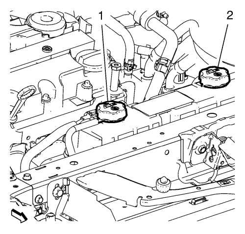
- Open the drive motor battery coolant reservoir cap (1).
- Open the drive motor generator power inverter module coolant reservoir cap (2).
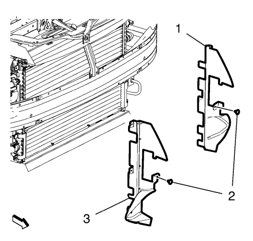
- Remove both front wheelhouse liners. Refer to Front Wheelhouse Front Liner Replacement .
- Remove the front bumper fascia. Refer to
Front Bumper Fascia Removal and Installation : Volt → Ampera .
- Place a basin underneath.
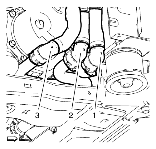
- Disconnect the drive motor battery radiator inlet pipe connector (1).
- Disconnect the drive motor battery coolant cooler outlet pipe connector (2).
- Disconnect the drive motor battery coolant cooler inlet pipe connector (3).
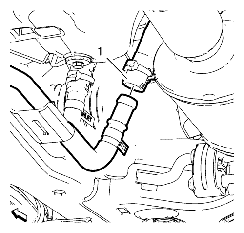
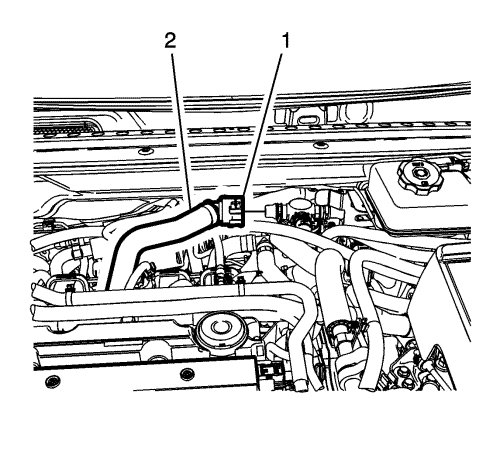
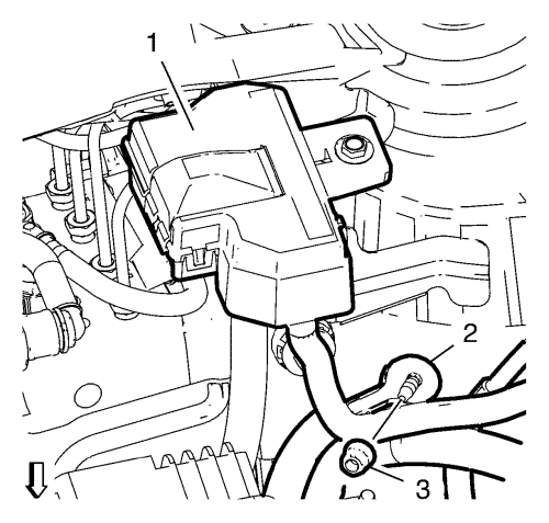
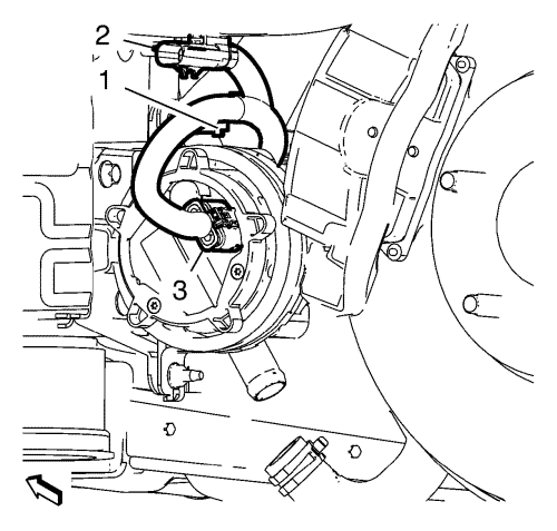
- Disconnect the heater water shutoff valve outlet hose (1).
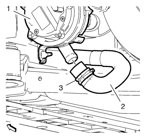
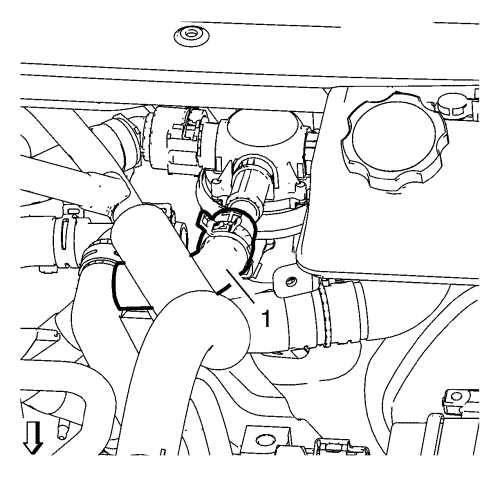
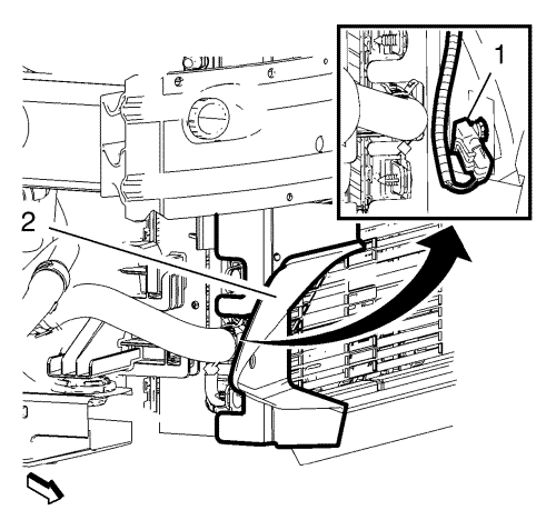
- Remove the clamp (3) and disconnect the drive motor power inverter module cooling outlet hose (2) from the drive motor power inverter module cooling pump (1).
- Drain the engine cooling system. Refer to Cooling System Draining and Filling .
- Recover the air conditioning refrigerant. Refer to
Refrigerant Recovery and Recharging : High Voltage Electric Compressor .
- Remove the drive motor generator power inverter module. Refer to Drive Motor Generator Power Inverter Module Replacement .
- Remove the air cleaner assembly. Refer to Air Cleaner Assembly Replacement .
- Remove the air cleaner resonator outlet duct. Refer to Air Cleaner Resonator Outlet Duct Replacement .
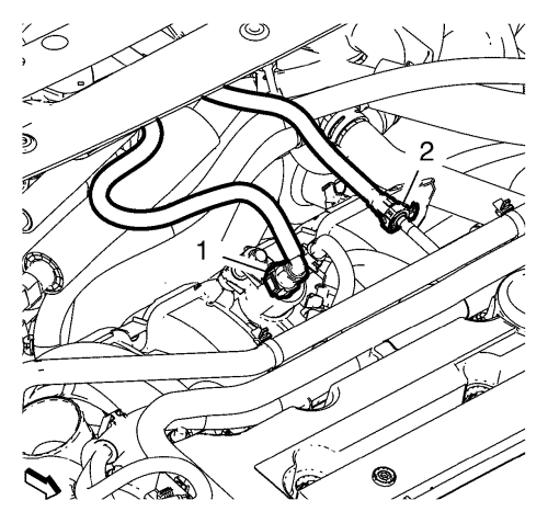
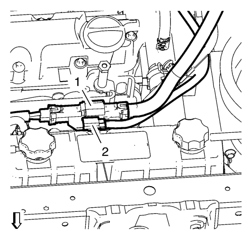
- Disconnect the canister purge pipe (1) from the canister purge valve. Refer to Plastic Collar Quick Connect Fitting Service .
- Plug the connections with the EN-6015 plugs .
- Disconnect the fuel feed pipe (2) from the fuel rail assembly. Refer to Plastic Collar Quick Connect Fitting Service .
- Plug the connections with the EN-6015 plugs .
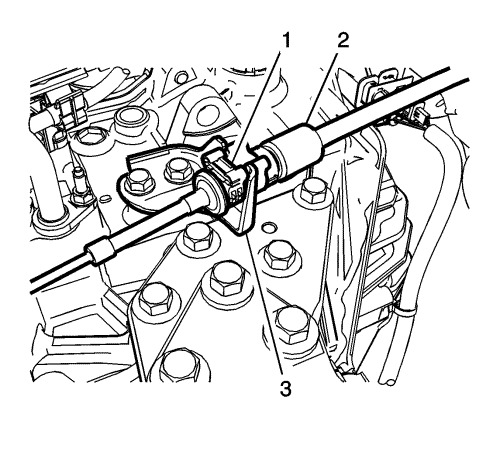
- Press the locking tab (1) rearward in order to release the transmission range selector lever cable (2) from the cable bracket.
- Disconnect the transmission range selector lever cable terminal (1) from the transmission manual pin, then position the cable out of the way.
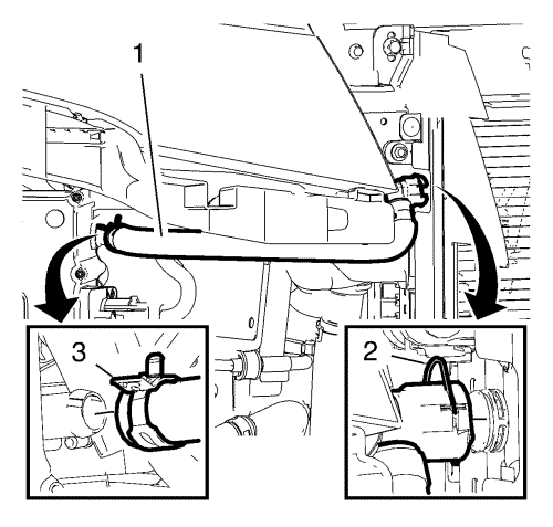
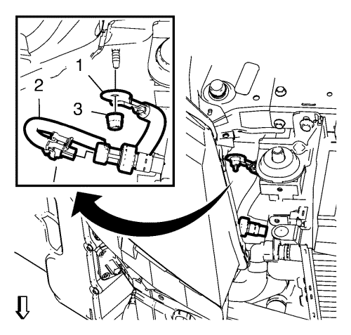
- Unlock the connector (1) and disconnect the heater water shutoff valve inlet hose (2) from the valve assembly.
- Disconnect the heater water shutoff valve outlet hose (1) from the valve assembly.
Note: Do not remove any hoses from the reservoir.
- Remove the engine coolant reservoir and lay down on the engine. Refer to Coolant Recovery Reservoir Replacement .
- Unlock the connector (2) and release the clamp (3).
- Remove the drive motor power inverter module coolant radiator hose (1).
- Disconnect the drive motor power inverter module cooling outlet hose (2) from the charger (1).
- Remove the nut (1) and separate the air conditioning compressor and evaporator hose (2) at the connection above the valve cover.
- Disconnect the air conditioning evaporator thermal expansion valve tube from the condenser. Refer to Air Conditioning Evaporator Thermal Expansion Valve Tube Replacement .
- Unclip the ambient temperature sensor (1) and the wiring harness from the radiator air baffle (2) and hang aside.
- Remove all radiator air baffle clips (2).
- Remove the left and the right radiator air baffles (1, 3).
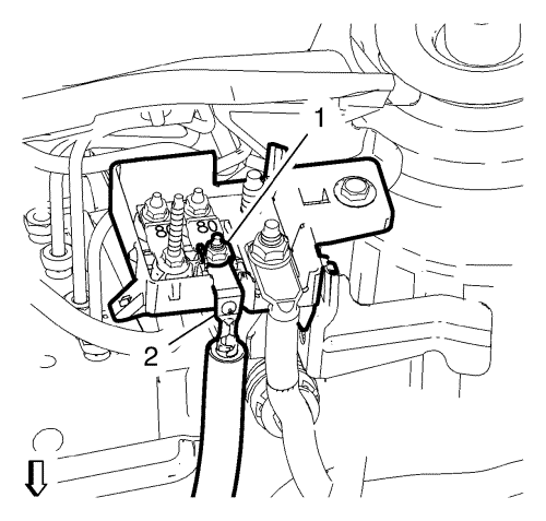
- Remove the ground cable nut (3) and the ground cable (1).
- Disconnect the AC pressure sensor wiring harness plug (2).
- Disconnect and unclip the coolant fan wiring harness plug (1).
- Remove the left headlamp. Refer to
Headlamp Replacement : Volt → Ampera .
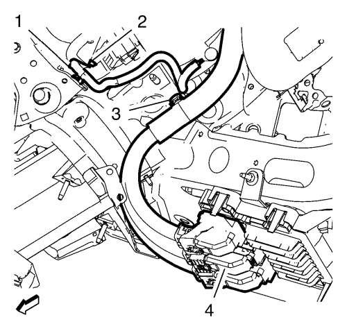
- Disconnect 3 ECM wiring harness plugs (4) and remove the clip (3).
- Unclip the drive motor power inverter module ground cable clip (3) and open the cable retainer (2).
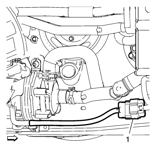
- Disconnect the wiring harness plug (1).
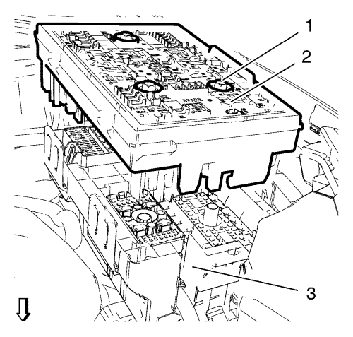
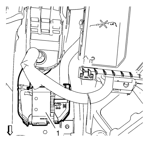
- Loosen the 3 bolts (1) of the accessory wiring junction block (2).
- Lift up the upper part of the accessory wiring junction block while uncliping it from the lower part of the accessory wiring junction block (3).
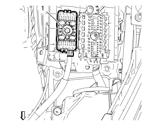
- Remove the wiring harness (1) from the lower part of the accessory wiring junction block and lay the wiring harness aside.
- Remove the electronic power steering (EPS) ground cable nut (3) and the EPS ground cable (2).
- Remove the cover (1).
- Remove the EPS power supply cable nut (1) and the EPS power supply cable (2).
- Lay EPS ground cable and power supply cable aside.
- Unclip the wiring harness from the transmission.
- Disconnect the Wiring Harness Plug (2). Refer to High Voltage Connectors .
- Disconnect the high voltage-wiring harness plug (1). Refer to High Voltage Connectors .
- Raise the vehicle. Refer to Lifting and Jacking the Vehicle .
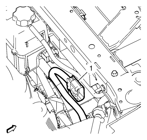
- Disconnect the heater water auxiliary pump wiring harness plug (1).
- Remove the ground cable nut (1) and unclip the ground cable (2).
- Disconnect the drive motor generator power inverter module coolant pump wiring harness plug (3) and unclip the clip (1).
- Disconnect and unclip the wiring harness plug (2).
- Disconnect the left and right wheel speed sensor wiring harness plug and unclip the wiring harness (1) from the lower control arms and the suspension frame, then position out of the way.
- Remove the left and right anti-roll bar links from the strut assemblies. Refer to Anti-roll Bar Link Replacement .
- Disconnect the steering linkage outer track rods from the steering knuckles. Refer to Steering Linkage Outer Track Rod Replacement .
- Disconnect the left and right lower control arms from the steering knuckles. Refer to Lower Control Arm Replacement .
- Disconnect the left and right front wheel shafts from the wheel hubs. Refer to Front Wheel Drive Shaft Replacement .
- Remove the catalytic converter. Refer to Catalytic Converter Replacement .
Note: The SPX installation manual is supplied with the special tool and is also available online from SPX directly. Go to www.spxtools-shop.com.
- Assemble the EN-49290 support tool (1) according to the details provided in the SPX installation manual.
- Support the CH-904 base frame on a jack.
- Support the EN-49290 support tool on the CH-904 base frame .
Note: The SPX installation manual is supplied with the special tool and is also available online from SPX directly. Go to www.spxtools-shop.com.
- Install the EN-49290 support tool (1) according to the details provided in the SPX manual.
- Lower the vehicle.
- Place the ECM and the accessory wiring junction block wiring harnesses on the top of engine assembly.
- Place all wiring harnesses and hoses on the powertrain unit if possible or ensure at least that they are free.
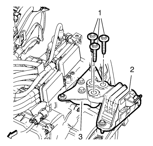
- Remove and DISCARD the 3 engine mount bolts (1) from the engine mount (3) and the engine mount bracket (2).
- Remove and DISCARD the 3 transmission mount bolts (1) from the transmission mount (2) and the transmission mount bracket (3).
- Raise the vehicle.
Note: The SPX installation manual is supplied with the special tool and is also available online from SPX directly. Go to www.spxtools-shop.com.
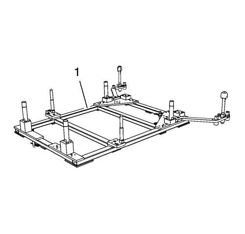
- Assemble the CH-49289 centring frame (1) according to the details provided in the SPX manual.
- Support the CH-904 base frame on a jack.
- Support the CH-49289 centring frame on the CH-904 base frame .
Note: The SPX installation manual is supplied with the special tool and is also available online from SPX directly. Go to www.spxtools-shop.com.
- Install the CH-49289 centring frame (1) according to the details provided in the SPX manual.
Note: Simplified graphic. Engine/transmission unit is fixed with engine support tool to suspension frame. Suspension frame is supported by centring adapter and underframe.
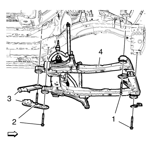
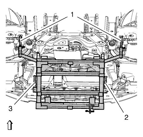
- Remove the suspension frame bolts (1, 2).
- Remove the frame reinforcements (3).
Note: A second technician is required.
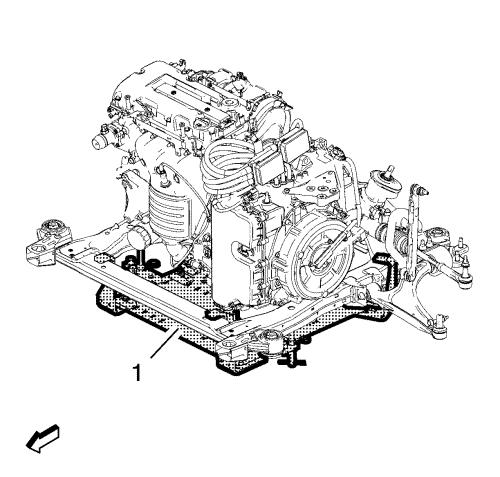
- Slowly and carefully lower the suspension frame (4) with the powertrain (PT) unit and the radiator assembly from the vehicle. Thereby take care on coolant hoses, wiring harnesses and other components which could be caught on the vehicle.
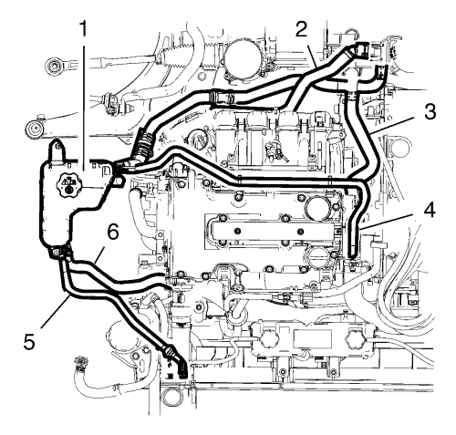
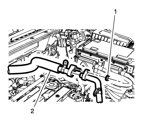
- Disconnect the coolant hose (6) from the radiator outlet hose tee.
- Disconnect the coolant vent hose (5) from the engine coolant radiator.
- Disconnect the engine coolant air bleed hose (4) from the water outlet.
- Disconnect the heater water shutoff valve inlet hose (2) from the water pump.
- Disconnect the heater water shutoff valve outlet hose (3) from the water outlet.
- Lay the engine coolant reservoir (1) along with the coolant hoses aside.
- Disconnect the radiator outlet hose (1) from the engine coolant thermostat housing.
- Disconnect the radiator inlet hose (2) from the water outlet.
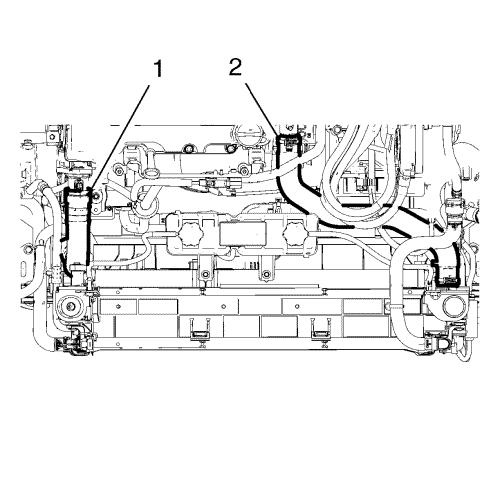
- Loosen the coolant hose assembly from the suspension frame.
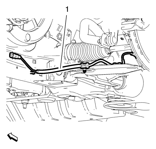
- Disconnect the transmission oil cooler pipes from the radiator. Refer to Transmission Fluid Cooler Hose/Pipe Quick-Connect Fitting Disconnection and Connection .
- Remove the entire radiator assembly from the suspension frame.
- Remove left and right front wheel drive shafts from the transmission. Refer to Front Wheel Drive Shaft Replacement .
- Disconnect and unclip all wiring harnesses and wiring harness plugs from the transmission.
- Disconnect the steering gear assist motor connectors. Refer to
FEP Connectors : Steering Gear .
- Install a suitable cable to the 3 engine lift brackets.
- Install a suitable engine lifting device to the cable.
- Extend the engine lifting device until the steel cables are slightly tensioned.
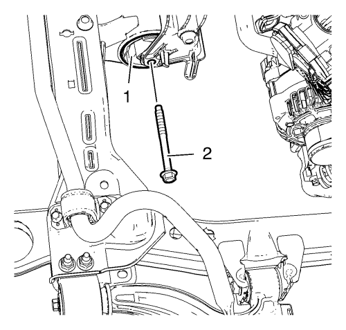
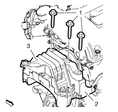
- Remove the rear transmission mount through bolt (2) from the rear transmission mount (1).
Note: A second technician is required.
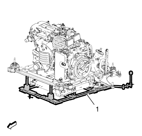
- Using the engine lifter, remove the PT-unit from the suspension frame.
- Lay the PT-unit down on a wooden pallet.
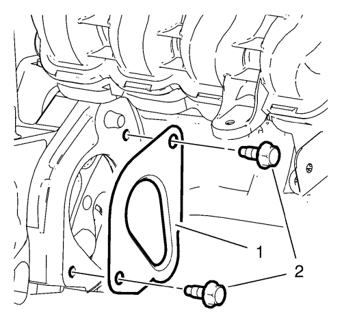
- Remove the 2 starter opening cover bolts (2).
- Remove the starter opening cover (1).
- Remove the 4 torque dampener bolts.
- Remove the 9 transmission fasteners.
Note: A second technician is required.
- Using an engine lifter, remove the transmission from the engine.
- Install the engine to a suitable engine stand.
- Transfer all parts as needed.
- Remove the engine from the engine stand and lay it down on a wooden pallet, using an engine lifter.
Note: A second technician is required.
- Position the engine to the transmission assembly.
Caution: Refer to Fastener Caution in the Preface section.
- Install the 9 transmission to engine fasteners and tighten to 80 N·m (59 lb ft).
- Install the 4 torque dampener bolts and tighten to 62 N·m (46 lb ft).
- Install the starter opening cover (2).
- Install the 2 starter opening cover bolts (2) and tighten to 20 N·m (15 lb ft).
- Using the engine lifter, position the PT-unit to the suspension frame.
- Install the rear transmission mount through bolt (2) to the rear transmission mount (1) and tighten to 100 N·m (74 lb ft).
- Remove the engine lifter from the engine lift brackets.
- Connect the steering gear assist motor connectors. Refer to
FEP Connectors : Steering Gear .
- Connect and clip in all wiring harnesses and wiring harness plugs to the transmission.
- Install left and right front wheel drive shafts to the transmission. Refer to Front Wheel Drive Shaft Replacement .
- Install the entire radiator assembly to the suspension frame.
- Fasten the coolant hose assembly to the suspension frame.
- Connect the radiator inlet hose (2) to the water outlet.
- Connect the radiator outlet hose (1) to the engine coolant thermostat housing.
- Connect the transmission oil cooler pipes to the radiator. Refer to Transmission Fluid Cooler Hose/Pipe Quick-Connect Fitting Disconnection and Connection .
- Connect the coolant hose (6) to the radiator outlet hose tee.
- Connect the coolant vent hose (5) to the engine coolant radiator.
- Connect the engine coolant air bleed hose (4) to the water outlet.
- Connect the heater water shutoff valve inlet hose (2) to the water pump.
- Connect the heater water shutoff valve outlet hose (3) to the water outlet.
- Lay the engine coolant reservoir (1) down on the engine.
Note: A second technician is required.
- Position the suspension frame with the PT-unit and the radiator assembly to the vehicle. Thereby take care on wiring harnesses, coolant hoses and other components.
- Position the suspension frame, so that the positioning pins (1) of the CH-49289 centring frame match to the appropriate under body holes.
- Install the frame reinforcements (3) and the frame reinforcement bolts. Hand tighten only.
- Install the 4 suspension frame bolts (1, 2) and tighten to 160 N·m (118 lb ft).
- Tighten the frame reinforcement bolts to 58 N·m (43 lb ft).
- Lower the CH-49289 centering frame (1) with the CH-904 base frame and a jack.
- Remove the CH-49289 centring frame (1) from the CH-904 base frame .
Note: The SPX installation manual is supplied with the special tool and is also available online from SPX directly. Go to www.spxtools-shop.com.
- Disassemble the CH-49289 centring frame (1) according to the details provided in the SPX manual.
- Lower the vehicle.
- Install the 3 NEW engine mount bolts (1) to the engine mount (3) and the engine mount bracket (2) and tighten to 58 N·m (43 lb ft).
Caution: Refer to Torque-to-Yield Fastener Caution in the Preface section.
- Install the 3 NEW transmission mount bolts (1) to the transmission mount (2) and the transmission mount bracket (3) and tighten in a first pass to 100 N·m (74 lb ft).
- Tighten the transmission mount bolts in a second pass to additional 90 - 105 degrees, using the EN-470-B meter .
- Raise the vehicle.
- Lower the EN-49290 support tool (1) with the CH-904 base frame and a jack.
- Remove the EN-49290 support tool (1) from the CH-904 base frame .
Note: The SPX installation manual is supplied with the special tool and is also available online from SPX directly. Go to www.spxtools-shop.com.
- Disassemble the EN-49290 support tool (1) according to the details provided in the SPX installation manual.
- Install the catalytic converter. Refer to Catalytic Converter Replacement .
- Connect the left and right front wheel shafts to the wheel hubs. Refer to Front Wheel Drive Shaft Replacement .
- Connect the left and right lower control arms to the steering knuckles. Refer to Lower Control Arm Replacement .
- Connect the steering linkage outer track rods to the steering knuckles. Refer to Steering Linkage Outer Track Rod Replacement .
- Install the left and right anti-roll bar links to the strut assemblies. Refer to Anti-roll Bar Link Replacement .
- Connect the left and right wheel speed sensor wiring harness plug and clip the wiring harness (1) to the lower control arms and the suspension frame.
- Connect the drive motor generator power inverter module coolant pump wiring harness plug (3) and clip in the clip (1).
- Connect and clip in the wiring harness plug (2).
- Install the ground cable (2).
- Install and tighten the cable nut (1)
- Connect the heater water auxiliary pump wiring harness plug (1).
- Lower the vehicle.
- Connect the high voltage wiring harness plug (1). Refer to High Voltage Connectors .
- Connect the wiring harness plug (2). Refer to High Voltage Connectors .
- Install the EPS power supply cable (2).
- Install and tighten the EPS power supply cable nut (1).
- Clip the wiring harness to the transmission.
- Install the EPS ground cable (2).
- Install and tighten the EPS ground cable nut (3).
- Install the cover (1).
- Install the wiring harness (1) to the lower part of the accessory wiring junction block.
- Clip the upper part of the accessory wiring junction block (2) to the lower part of the accessory wiring junction block (3).
- Tighten the 3 bolts (1) of the accessory wiring junction block (2) to 10 N·m(89 lb in).
- Connect the wiring harness plug (1).
- Connect 3 ECM wiring harness plugs (4) and install the clip (3).
- Clip the drive motor power inverter module ground cable clip (3) and close the cable retainer (2).
- Install the left headlamp. Refer to
Headlamp Replacement : Volt → Ampera .
- Connect and clip in the coolant fan wiring harness plug (1).
- Install the ground cable (1) and the ground cable nut (3) and tighten.
- Connect the A/C pressure sensor wiring harness plug (2).
- Install the left and the right radiator air baffles (1, 3).
- Install all radiator air baffle clips (2).
- Clip in the ambient temperature sensor (1) and the wiring harness to the radiator air baffle (2).
- Install the air conditioning compressor and evaporator hose (2) at the connection above the valve cover.
- Install the nut (1) and tighten to 22 N·m(16 lb ft).
- Connect the air conditioning evaporator thermal expansion valve tube to the condenser. Refer to Air Conditioning Evaporator Thermal Expansion Valve Tube Replacement .
- Connect the drive motor power inverter module cooling outlet hose (2) to the charger (1).
- Install the drive motor power inverter module coolant radiator hose (1).
- Lock the connector (2) and fasten the clamp (3).
- Reposition and tighten the engine coolant reservoir. Refer to Coolant Recovery Reservoir Replacement .
- Connect the heater water shutoff valve outlet hose (1) to the valve assembly.
- Connect the heater water shutoff valve inlet hose (2) to the valve assembly and lock the connector (1).
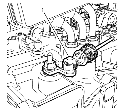
- Connect the transmission range selector lever cable terminal (1) to the transmission manual pin.
- Press the locking tab (1) forward in order to lock the transmission range selector lever cable (2) to the cable bracket.
- Connect the canister purge pipe (1) to the canister purge valve. Refer to Plastic Collar Quick Connect Fitting Service .
- Connect the fuel feed pipe (2) to the fuel rail assembly. Refer to Plastic Collar Quick Connect Fitting Service .
- Connect the fuel feed pipe (1) to the fuel rail assembly. Refer to
Fuel Feed Pipe Replacement : Chassis → Engine Compartment .
- Raise the vehicle.
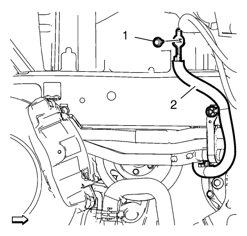
- Connect the drive motor generator module cooling outlet hose (2) to the drive motor generator module cooling pump (1) and install the clamp (3).
- Connect the heater water shutoff valve outlet hose (1).
- Connect the drive motor battery radiator inlet pipe connector (1).
- Connect the drive motor battery coolant cooler outlet pipe connector (2).
- Connect the drive motor battery coolant cooler inlet pipe connector (3).
- Install both front wheelhouse liners. Refer to Front Wheelhouse Front Liner Replacement .
- Install the front bumper fascia. Refer to
Front Bumper Fascia Removal and Installation : Volt → Ampera .
- Lower the vehicle.
- Install the air cleaner resonator outlet duct. Refer to Air Cleaner Resonator Outlet Duct Replacement .
- Install the air cleaner assembly. Refer to Air Cleaner Assembly Replacement .
Note: High voltage system stays disabled.
- Install the drive motor generator power inverter module. Refer to Drive Motor Generator Power Inverter Module Replacement .
- Fill the engine cooling system. Refer to Cooling System Draining and Filling .
- Fill the drive motor generator battery cooling system. Refer to Drive Motor Battery Cooling System Draining and Filling .
- Fill the drive motor generator cooling system. Refer to Drive Motor Generator Power Inverter Module Cooling System Draining and Filling .
- Charge the air conditioning system. Refer to
Refrigerant Recovery and Recharging : High Voltage Electric Compressor .
- Check engine oil level. Refer to Engine Oil and Oil Filter Replacement .
Danger: Always perform the High Voltage Disabling procedure prior to servicing any High Voltage component or connection. Personal Protection Equipment (PPE) and proper procedures must be followed.
The High Voltage Disabling procedure will perform the following tasks:
| • | Identify how to disable high voltage. |
| • | Identify how to test for the presence of high voltage. |
| • | Identify condition under which high voltage is always present and personal protection equipment (PPE) and proper procedures must be followed. |
- Enable the high voltage system. Refer to High Voltage Enabling .
- Connect the intermediate steering shaft to the steering gear. Refer to Intermediate Steering Shaft Replacement .
- Check and correct transmission fluid level. Refer to Transmission Fluid Level and Condition Check .


