MAINTENANCE AND REPAIR
ON-VEHICLE SERVICE


Fuel System Pressure Relief
Procedure
Caution : The fuel system is under pressure. To avoid fuel spillage and the risk of personal injury or fire, it is necessary to relieve the fuel system pressure before disconnecting the fuel lines.
- Remove the fuel cap.
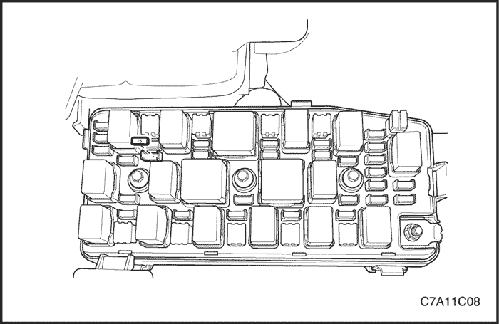
- Remove the fuel pump fuse from the engine fuse block.
- Start the engine and allow the engine to stall.
- Crank the engine for an additional 10 seconds.
Fuel Pressure Test
Test Procedure
Caution : The fuel system is under pressure. To avoid fuel spillage and the risk of personal injury or fire, it is necessary to relieve the fuel system pressure before disconnecting the fuel system.
- Relieve the fuel system pressure. Refer to "Fuel System Pressure Relief" in this section.
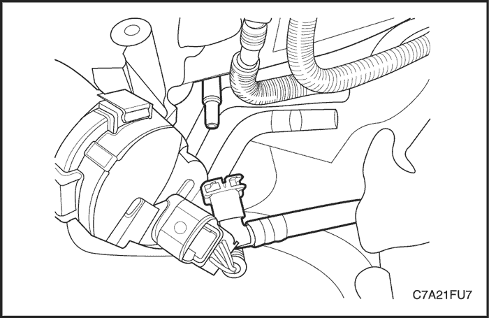
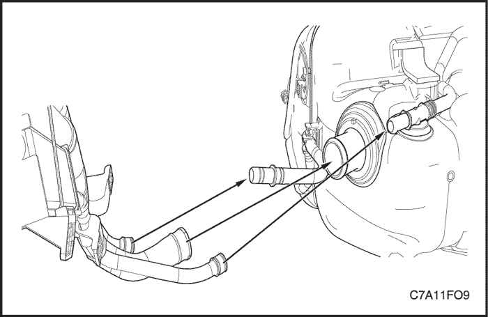
- Disconnect the fuel feed line from the fuel rail.
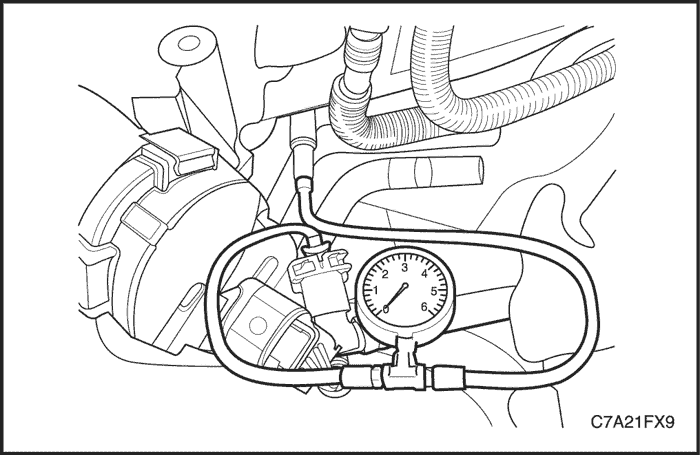
- Connect the fuel pressure gauge connector to the fuel rail.
- Connect the fuel pressure gauge connector to the fuel feed line.
- Check the fuel leakage.
- Read the fuel pressure gauge. Normal fuel pressure is in the range of 402 ~ 418 kPa (58.3 ~ 60.6 psi).
- Relieve the fuel pressure.
- Remove the fuel pressure gauge.
- Connect the fuel feed line to the fuel rail.
- Start the engine and check for the fuel leakage.
Fuel Tank
Removal Procedure
Caution : Do not allow smoking or the use of open flames in the area where work on the fuel or EVAP system is taking place. Anytime work is being done on the fuel system, disconnect the negative battery cable, except for those tests where battery voltage is required.
Caution : The fuel system is under pressure. To avoid fuel spillage and the risk of personal injury or fire, it is necessary to relieve the fuel system pressure before disconnecting the fuel lines.
- Disconnect the negative battery cable.
- Drain the fuel tank. Ensure that the fuel level in the tank is less than1/4 full. If necessary, drain the fuel tank to at least this level.
- Relieve the fuel system pressure. Refer to "Fuel System Pressure Relief" in this section.
- Raise and support the vehicle.
- Remove the front muffler. Refer to Section 1G3, Engine Exhaust - HFV6 3.2L.
- Remove the propeller shaft and rear drive module (RDM). Refer to Section 3B, Rear Drive Axle.
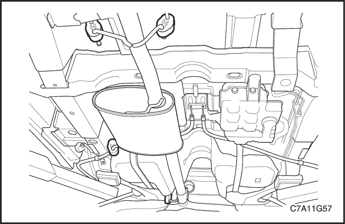
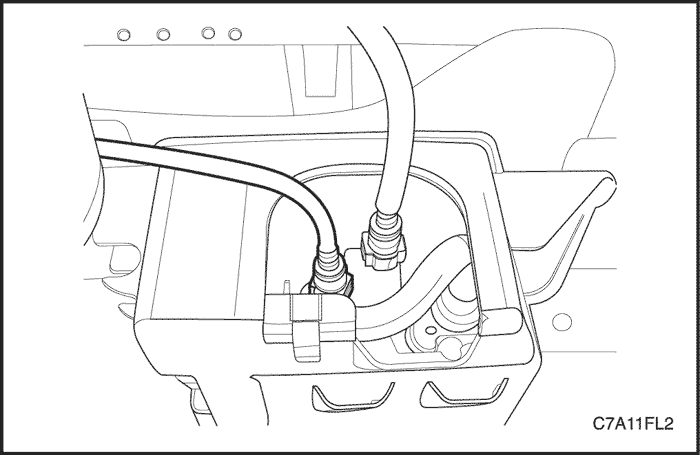
- Disconnect the fuel pump connector at the right rear side of the fuel tank.
- Disconnect the fuel tank filler tube, EVAP vent hose and vapor hose from the fuel tank.
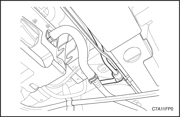
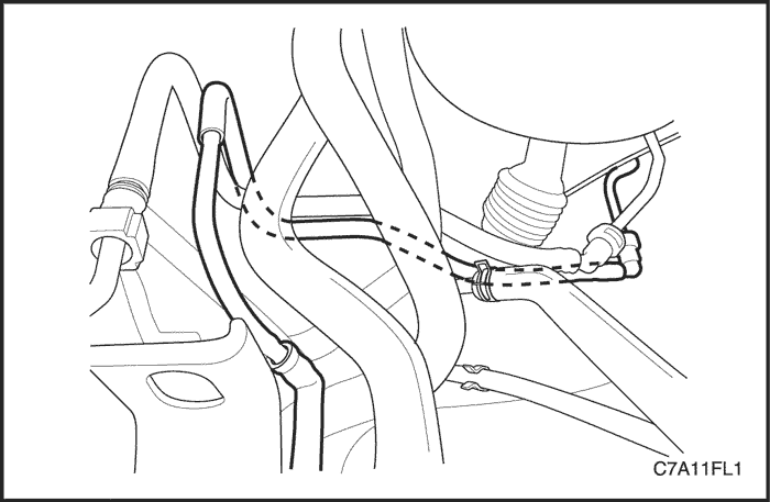
- Disconnect the fuel feed line near the right front side of the fuel tank.
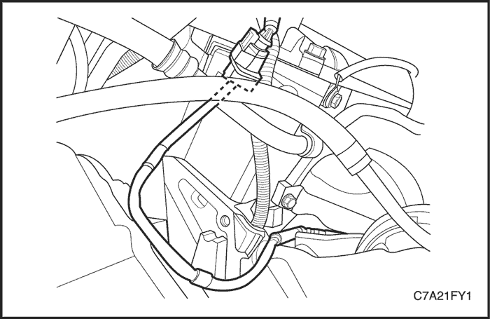
- Disconnect the fuel vapor pipe from the EVAP emission canister.
- Support the fuel tank.
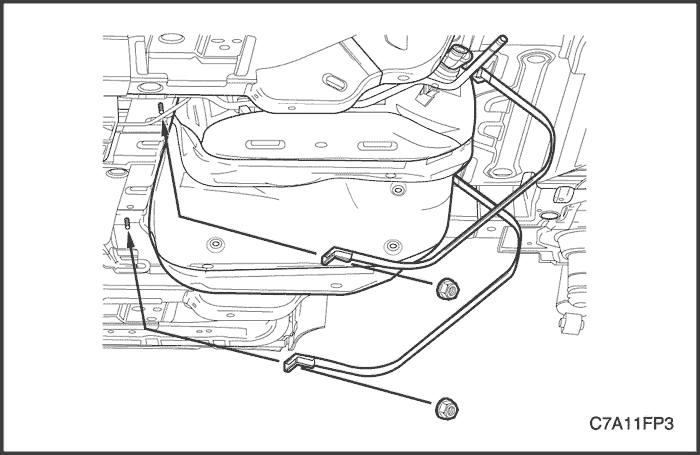
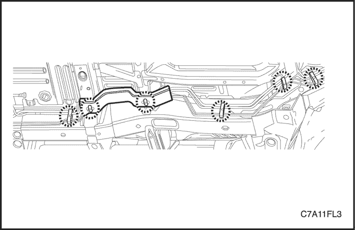
- Remove the parking brake cables support bracket bolts and move it away from the fuel tank.
- Remove the fuel tank strap retaining nuts.
- Remove the fuel tank straps.
- Carefully lower the jack and move the front of the fuel pump downward while tilting the rear of the fuel pump upward.
- Remove the fuel tank.
Installation Procedure
- Install the fuel tank in the position previously removed.
- Install the fuel tank straps.
Tighten
Tighten the fuel tank strap retaining nuts to 20 N•m (15 lb-ft).
- Install the parking brake cables support bracket bolts.
- Connect the fuel vapor pipe to the EVAP emission canister.
- Connect the fuel feed line near the right front side of the fuel tank.
- Connect the fuel tank filler tube, EVAP vent hose and vapor hose to the fuel tank.
- Connect the fuel pump connector at the right rear side of the fuel tank.
- Install the parking brake cables support bracket. Refer to Section 4G, Parking Brake.
- Install the front muffler. Refer to Section 1G3, Engine Exhaust - HFV6 3.2L.
- Install the propeller shaft and RDM. Refer to Section 3B, Rear Drive Axle.
- Fill the fuel tank.
- Connect the negative battery cable.
- Perform a leak check of the fuel tank and the fuel line connections.
Fuel Pump Assembly
Tools Required
Main Fuel Pump Locking Ring Remover/Installer EN-48279
Sub Fuel Pump Locking Ring Remover/Installer EN-48278
Removal Procedure
Caution : The fuel system is under pressure. To avoid fuel spillage and the risk of personal injury or fire, it is necessary to relieve the fuel system pressure before disconnecting the fuel lines.
- Relieve the fuel system pressure. Refer to "Fuel System Pressure Relief"
- Disconnect the negative battery cable.
- Fold the rear seat.
- Lift up the carpet and the insulation.
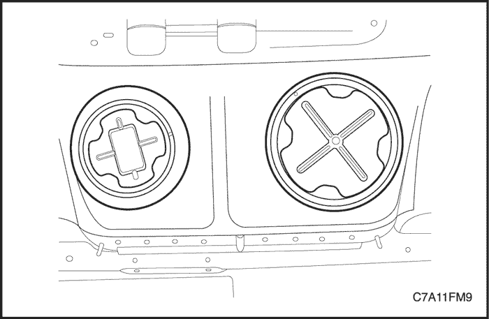
- Remove the main and sub fuel pump access covers.
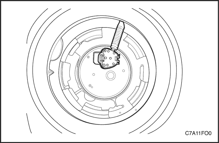
- Disconnect the electrical connector at the sub fuel pump assembly.
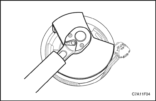
- Install the sub fuel pump lock ring remover/installer EN-48278 to the sub fuel pump and turn it counterclockwise.
- Remove the sub fuel pump lock ring.
Notice : Be careful not to damage the fuel sender for the correct fuel leveling while removing the fuel pump assembly from the fuel tank.
- Remove the sub fuel pump assembly and the O-ring from the fuel tank.
Notice : O-ring should not be contaminated by fuel.
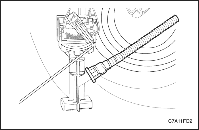
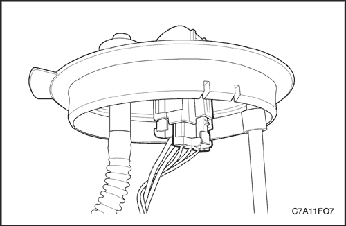
- Disconnect the main fuel pump-to-sub fuel pump connecting hose at the sub fuel pump.
- Disconnect the electrical connector at the main fuel pump assembly.
- Disconnect the fuel feed line.
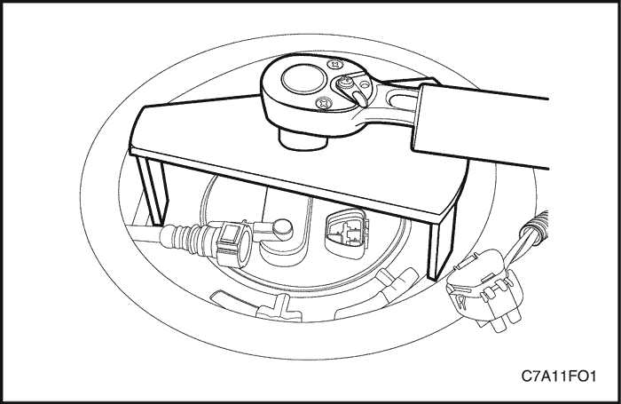
- Install the main fuel pump lock ring remover/installer EN-48279 to the main fuel pump and turn it counterclockwise.
- Remove the main fuel pump lock ring.
Notice : Be careful not to damage the fuel sender for the correct fuel leveling while removing the fuel pump assembly from the fuel tank.
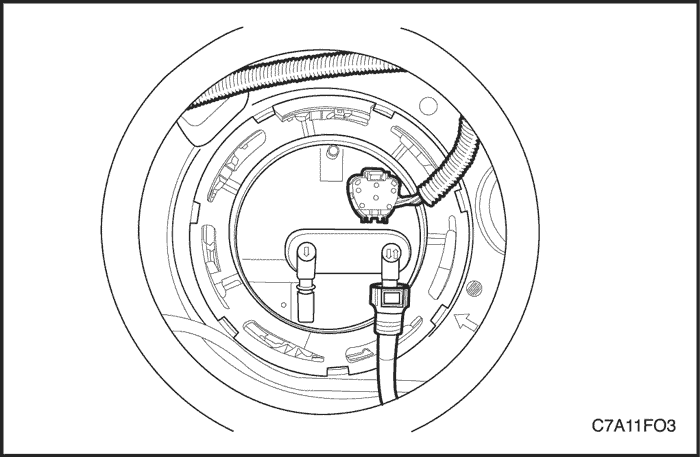
- Remove the main fuel pump assembly and the O-ring from the fuel tank.
Notice : O-ring should not be contaminated by fuel.
Installation Procedure
- Clean all of the mating surface on the both fuel pump and fuel tank.
Notice : For ease of the main fuel pump-to-sub fuel pump connecting hose, install the main fuel pump assembly first.
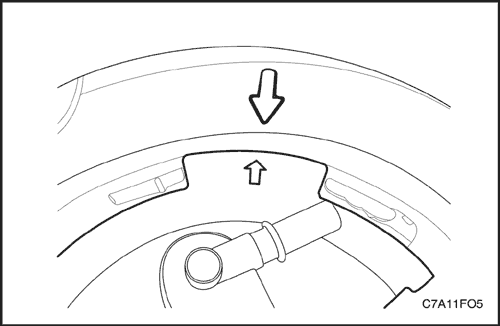
Notice : Be sure that the arrow on the main fuel pump assembly should be aligned with the arrow on the fuel tank.
Notice : Be careful not to damage the fuel sender for the correct fuel leveling while installing the fuel pump assembly to the fuel tank.
Caution : Do not reuse the main fuel pump O-ring.
- Position the new main fuel pump O-ring and the main fuel pump first into the fuel tank in the same location as removed.
- Pull the main fuel pump-to-sub fuel pump connecting hose towards the sub fuel pump assembly.
- Connect the main fuel pump-to-sub fuel pump connecting hose at the sub fuel pump.
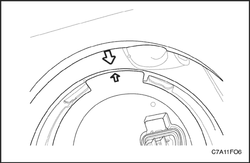
Notice : Be sure that the arrow on the sub fuel pump assembly should be aligned with the arrow on the fuel tank.
Notice : Be careful not to damage the fuel sender for the correct fuel leveling while installing the fuel pump assembly to the fuel tank.
Caution : Do not reuse the sub fuel pump O-ring.
- Position the new sub fuel pump O-ring and the sub fuel pump into the fuel tank in the same location as removed.
- Install the sub fuel pump lock ring by turning the sub fuel pump lock ring remover/installer EN-48278 clockwise.
- Connect the electrical connector at the sub fuel pump.
- Install the main fuel pump lock ring by turning the main fuel pump lock ring remover/installer EN-48279 clockwise.
- Connect the electrical connector at the main fuel pump.
- Connect the fuel feed line.
- Install the main and sub fuel pump access covers.
- Connect the negative battery cable.
- Perform an operational check of the fuel pump.
- Fold the rear seat back to the original position.
Fuel Sender
Replacement Procedure
Notice : The illustrations in this section show the fuel sender on the main fuel pump ONLY. The fuel sender on the sub fuel pump is similar.
Notice : Be careful not to damage the fuel sender for the correct fuel leveling while removing or installing the fuel pump assembly from the fuel tank.
- Remove the fuel pump assembly. Refer to "Fuel Pump Assembly" in this section.
- Disconnect the fuel sender connector.
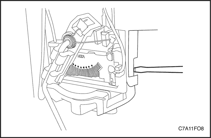
- Press the locking tap by using a suitable tool such as a screwdriver.
- Remove the fuel sender assembly by sliding it out from the fuel pump.
Notice : Improper installation of the fuel sender on the fuel pump may cause the incorrect fuel leveling.
- Install the fuel sender in the reverse order of removal.
- Install the fuel pump assembly into the fuel tank. Refer to "Fuel Pump Assembly" in this section.
Fuel Filter
Notice : The fuel filter is assembled within the fuel pump. It cannot be replaced separately. The fuel filter should be replaced as a fuel pump assembly, if needed. Refer to "Fuel Pump" in this section.
Fuel Rail Assembly
Removal Procedure
- Disconnect the negative battery cable.
- Relieve the fuel system pressure. Refer to "Fuel System Pressure Relief" in this section.
- Remove the upper intake manifold assembly. Refer to Section 1C2, Engine Mechanical - HFV6 3.2L.
- Disconnect the fuel feed line from the fuel rail.
Caution : Clean around the area where the fuel injectors enter the lower intake manifold.
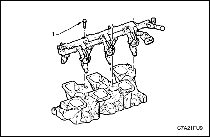
- Remove the bolt (1), three places, attaching the fuel rail to the lower intake manifold.
Caution : Care must be taken when removing the fuel rail and injector assembly to prevent damage to the injector spray tips and injector harness connector terminals. Support the fuel rail and injector assembly after removal.
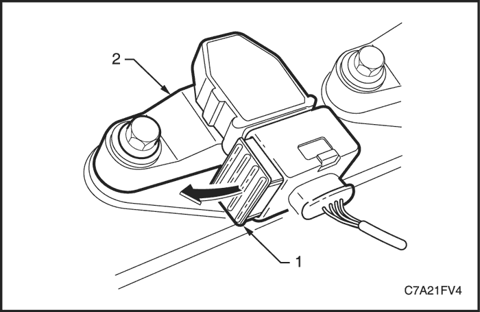
- Slide the fuel injector wiring connector locking tab (1) upwards in the direction of the arrow.
- Disconnect the connector from the fuel injector.
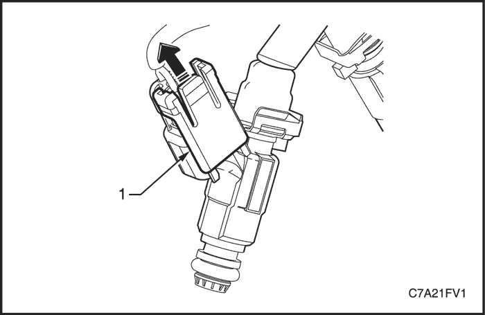
- Slide the fuel injector wiring connector locking tab (1) upwards in the direction of the arrow.
- Disconnect the connector from the fuel injector.
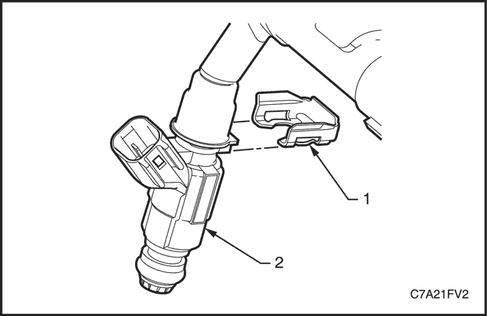
- Using a flat blade screwdriver, remove the fuel injector retaining clip (1) from the fuel injector (2). Discard the retaining clip.
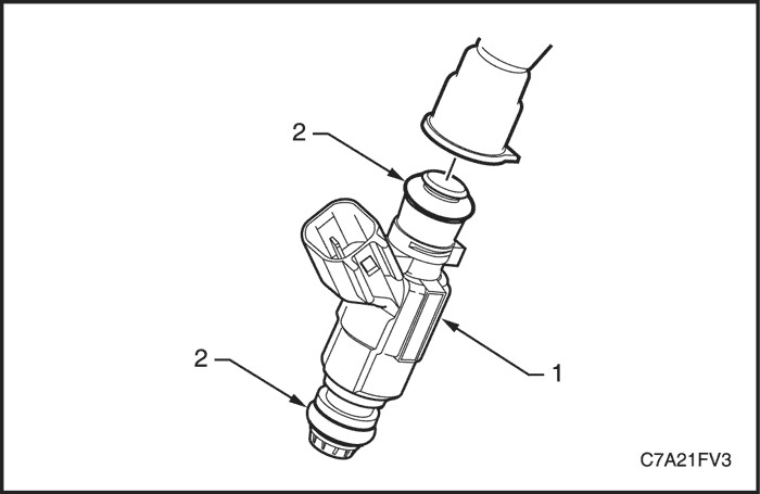
- Remove the fuel injector (1) from the fuel rail.
- Remove and discard the fuel injector seals (2).
Installation Procedure
- Install new fuel injector seals and lubricate with clean engine oil.
- Install the fuel injector (2) to the fuel rail.
- Install a new fuel injector retaining clip (1).
- Connect the fuel injector connector.
- Carefully install the fuel rail and injector assembly.
Caution : Ensure the fuel injectors are correctly seated in the lower intake manifold, and the fuel rail attaching brackets are correctly located prior to tightening the attaching bolts.
- Install the fuel rail assembly attaching bolts (1).
Tighten
Tighten the fuel rail assembly attaching bolts to 10 N•m (89 lb-in).
- Connect the fuel feed hose to the fuel rail.
- Inspect the fuel rail and quick connect fitting for leaks.
Ignition Coil
Removal Procedure
- Disconnect the negative battery cable.
- Remove the engine dress cover. Refer to Section 1C2, Engine Mechanical - HFV6 3.2L.
Note : If the upper intake manifold has been removed, plug the lower manifold openings to prevent dirt and other contaminants from entering.
- If required, remove the upper intake manifold assembly. Refer to Section 1C2, Engine Mechanical - HFV6 3.2L.
- Using a flat-blade screwdriver, slide the connector retaining latch (1) in the direction of the arrow.
- Remove the wiring harness connector from the ignition coil (2).
Caution : Clean the area around the ignition coil before removal to avoid debris from entering the engine.
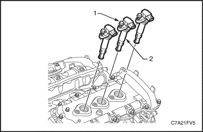
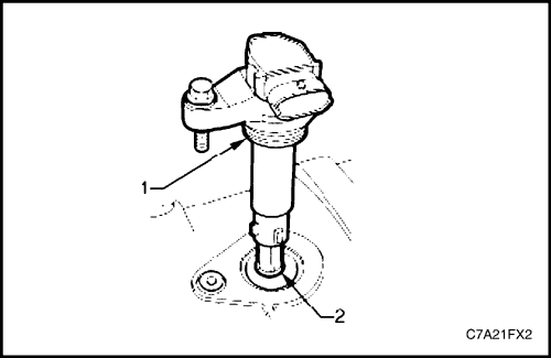
- Fully loosen the bolt (1) attaching the ignition coil (2) to the camshaft cover.
Note : The ignition coil bolts are captive. Do not attempt to remove the bolts from the ignition coil.
- Remove the ignition coil by first, twisting the coil to release it, and then pulling the ignition coil upwards to remove it.
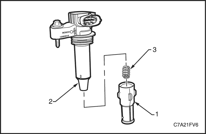
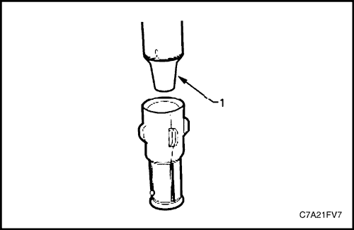
Caution : Do not use a sharp implement such as a knife to cut the ignition coil boot (1) from the ignition coil. Using a sharp implement may damage the ignition coil insulator (2).
- Using your thumb, work the ignition coil boot off the ignition coil insulator.
Note : Take care the spring (3) does not become dislodged as the boot is removed. To aid removal of the boot, use a blunt instrument to lift the boot edge away from the coil insulator and spray a release agent between the boot and the coil insulator.
- Remove the spring from the ignition coil insulator.
Installation Procedure
- Position the spring in the insulator recess.
- Lubricate the ignition coil insulator (1) with talcum powder.
- Fit the ignition coil boot, ensuring it is fully seated at the top of the insulator.
- Lubricate the ignition coil sealing rubber (1) with clean engine oil, and the inside of the ignition coil boot (2) with talcum powder.
- Install the ignition coil by pushing down on the ignition coil to engage the sealing rubber in the cylinder head cover.
Caution : Ensure the ignition coil is fully seated before tightening the attaching bolt to the specified torque.
- Install the ignition coil attaching bolt.
Tighten
Tighten the ignition coil attaching bolt to 9 N•m (80 lb-in).
Spark Plug
Removal Procedure
- Disconnect the negative battery cable.
- Remove the engine dress cover. Refer to Section 1C2, Engine Mechanical - HFV6 3.2L.
- Remove the ignition coil retaining bolts (1) and remove the ignition coils (2). Refer to "Ignition Coil" in this section.
Caution : Allow the engine to cool (to at least 50(C) before attempting to remove spark plugs. Attempting to remove spark plugs from a hot engine may cause the plug / cylinder head threads to bind, resulting in tearing of the alloy cylinder head threads.
- Using a suitable spark plug socket, loosen the spark plug slightly and then re-tighten to break away any carbon deposits on the threads.
- Loosen the spark plug once again one or two turns, then use compressed air to remove any foreign material that may otherwise enter the combustion chamber.
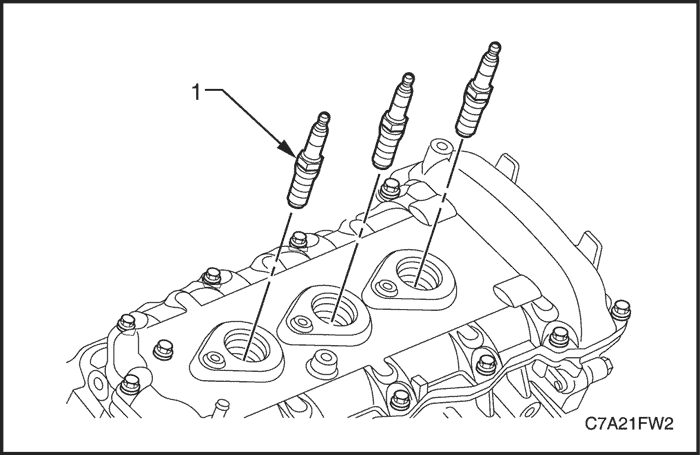
- Remove the spark plug (1).
- Repeat as required for the remaining spark plugs.
Note :
- Place each spark plug in the same order as that of removal. This will enable any abnormal spark plug condition to be identified with the cylinder.
- If the spark plugs are removed for an indefinite period before installation, plug the spark plug openings to prevent foreign particle ingress.
- Use a feeler gauge to check the spark plug gap. If the gap is not within specifications, replace the spark plug.
Caution : Under no circumstances should the spark plug/s gap be adjusted. If the gap is not within specifications, replace the spark plug.
- Inspect the spark plugs if required. Refer to Section 1A3, General Engine Information - HFV6 3.2L.
Installation Procedure
Caution : Do not use anti-seize compound or similar lubricant on the spark plug threads.
- Using a suitably sized rubber tube attached to the spark plug terminal post, hands start each spark plug into the cylinder head thread.
Caution : Failure to tighten a spark plug to the correct torque specification may result in premature spark plug failure, and / or engine damage.
Tighten
Tighten the spark plug to 18 N•m (13 lb-ft).
Throttle Body Assembly
Removal Procedure
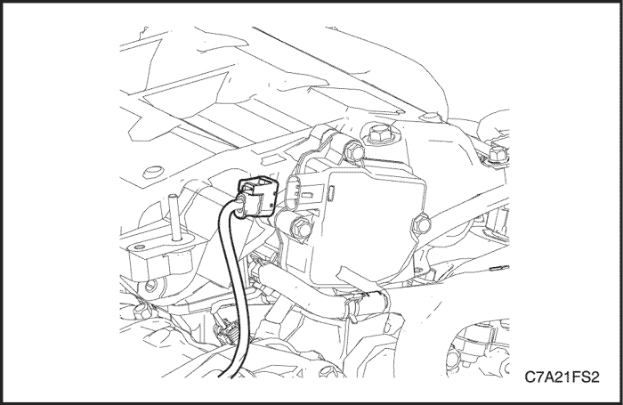
- Disconnect the negative battery cable.
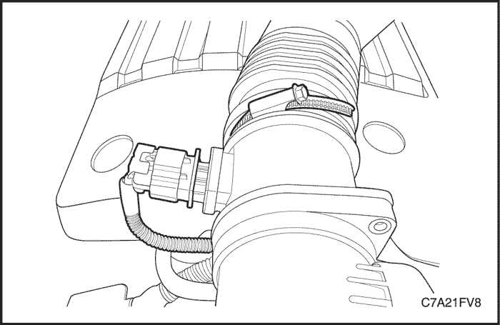
- Disconnect the positive crankcase ventilation (PCV) hose from the air intake duct.
- Disconnect the air intake duct from the throttle body.
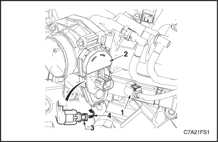
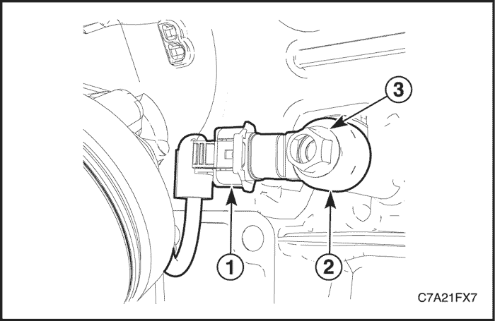
Caution : The following precautions must be followed when disconnecting the throttle body wiring connector.
- Do not use any mechanical device such as a screwdriver to disengage the harness connector (1) from the throttle body (2).
- When retracting the throttle wiring connector lock (3), take care not to disengage the lock from the connector.
- Do not pull on the connector wires.
- Retract the throttle body wiring connector lock (3).
- While pressing the connector latch in the direction of the arrow (4), disconnect the throttle body wiring connector.
- Disconnect the throttle body connector.
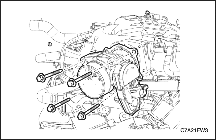
- Remove the four bolts, attaching the throttle body to the upper intake manifold.
- Remove the throttle body and gasket.
Installation Procedure
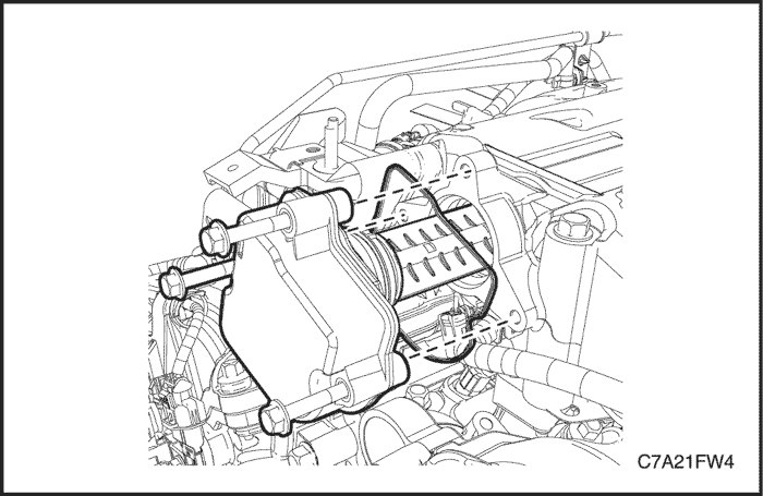
- Ensure the throttle body and upper intake manifold mating surfaces are clean and free of foreign material.
- Install the throttle body with a new throttle body to upper intake manifold gasket.
Tighten
Tighten the throttle body assembly attaching bolts to 10 N•m (89 lb-in).
- Connect the wiring harness connector to the throttle body, ensuring the connector latch and connector slide have fully engaged.
Intake Manifold Tuning Control Solenoid Valve
Removal Procedure
- Disconnect the negative battery cable.
- Disconnect the intake manifold tuning control (IMTC) solenoid valve connector.
- Remove the upper intake manifold assembly. Refer to Section 1C2, Engine Mechanical - HFV6 3.2L.
- Remove the three bolts, attaching the IMTC solenoid valve to the upper intake manifold.
- Remove the IMTC solenoid valve from the upper intake manifold by first twisting the solenoid valve to release it, and then pulling the solenoid valve away from the manifold.
Installation Procedure
- Install the IMTC solenoid valve to the upper intake manifold.
Caution : Ensure the IMTC solenoid valve is fully seated before tightening the attaching bolt to the specified torque.
Tighten
Tighten the intake manifold tuning control solenoid valve attaching bolts to 10 N•m (89 lb-in).
- Install the upper intake manifold. Refer to Section 1C2, Engine Mechanical - HFV6 3.2L.
- Connect the IMTC solenoid valve connector.
Mass Air Flow (MAF) Sensor Assembly
Removal Procedure
- Disconnect the negative battery cable.
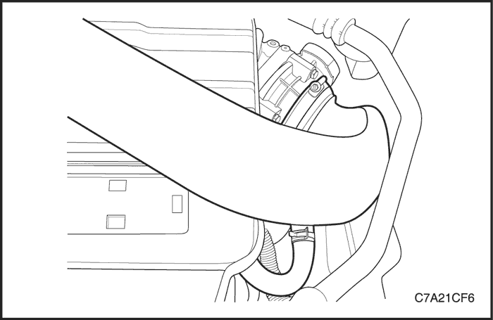
- Loosen the clamp and pull the flexible air intake duct away from the mass air flow (MAF) sensor assembly.
- Disconnect the MAF sensor connector.
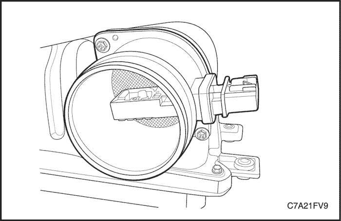
- Remove the screw, two places, attaching the MAF sensor assembly (2) to the upper air cleaner housing (3).
- Remove the MAF sensor assembly.
Installation Procedure
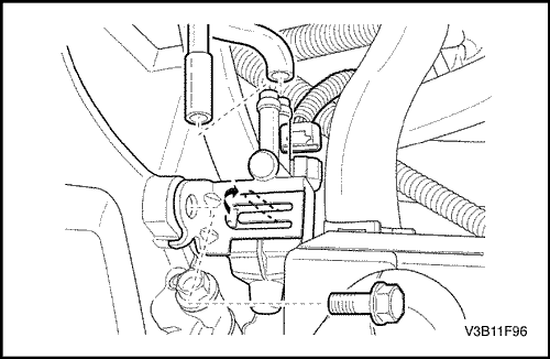
Caution : Ensure that the arrow on the MAF sensor housing face toward the air flow direction.
- Install the MAF sensor assembly to the air cleaner upper housing.
Tighten
Tighten the mass air flow sensor assembly attaching screws to 2 N•m (18 lb-in).
- Connect the flexible air intake duct and tighten the clamp.
- Connect the MAF sensor connector.
Knock Sensor
Removal Procedure
Bank 1
- Disconnect the negative battery cable.
- Remove the exhaust front pipe. Refer to Section 1G3, Engine Exhaust - HFV6 3.2L.
- Remove the rear pup converter. Refer to Section 1G3, Engine Exhaust - HFV6 3.2L.
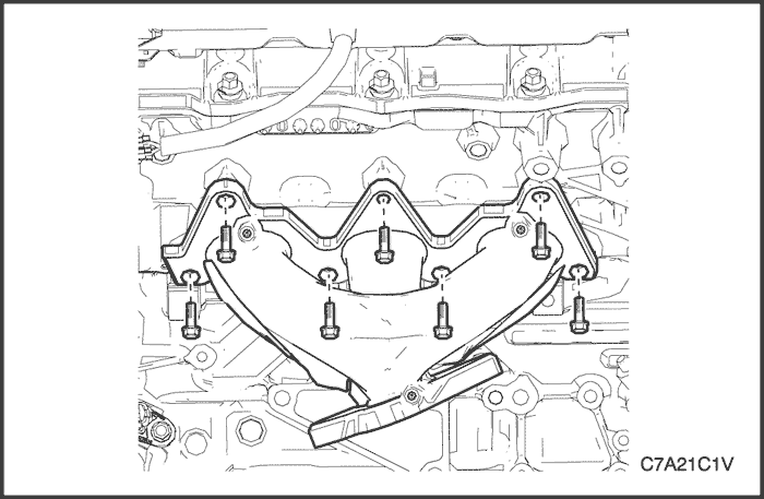
- Remove the rear exhaust manifold. Refer to Section 1C2, Engine Mechanical - HFV6 3.2L.
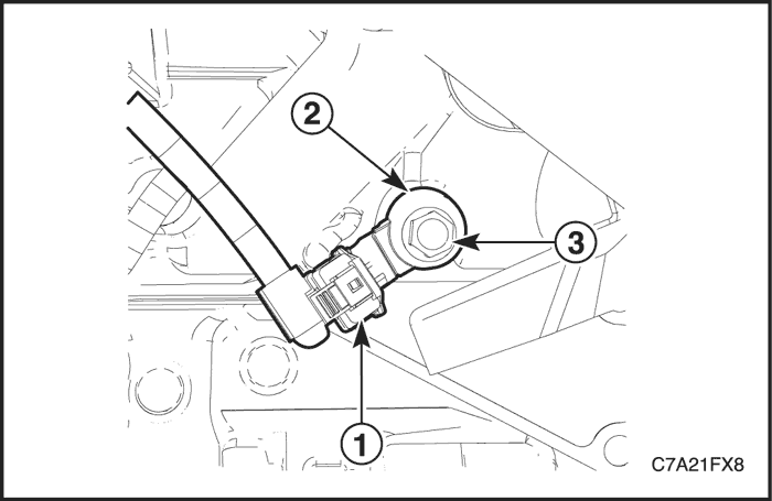
- Disconnect the wiring harness connector (1) from the knock sensor (2).
- Remove the bolt (3) attaching the knock sensor (2) to the engine block, and remove the knock sensor.
Bank 2
- Disconnect the negative battery cable.
- Remove the exhaust front pipe. Refer to Section 1G3, Engine Exhaust - HFV6 3.2L.
- Remove the front pup converter. Refer to Section 1G3, Engine Exhaust - HFV6 3.2L.
- Disconnect the wiring harness connector (1) from the knock sensor (2).
- Remove the bolt (3) attaching the knock sensor (2) to the engine block and remove the knock sensor.
Installation Procedure
Bank 1
- Ensure the knock sensor mounting surface is flat and free of any dirt, oxidisation, etc.
Caution : Do not over-tighten the attaching bolt as incorrect operation of the knock sensor may result.
- Install the knock sensor (2) and bolt (3).
Tighten
Tighten the knock sensor to 23 N•m (17 lb-ft).
- Connect the knock sensor connector (1).
Bank 2
- Ensure the knock sensor mounting surface is flat and free of any dirt, oxidisation, etc.
Caution : Do not over-tighten the attaching bolt as incorrect operation of the knock sensor may result.
- Install the knock sensor (2) and bolt (3).
Tighten
Tighten the knock sensor to 23 N•m (17 lb-ft).
- Connect the knock sensor connector (1).
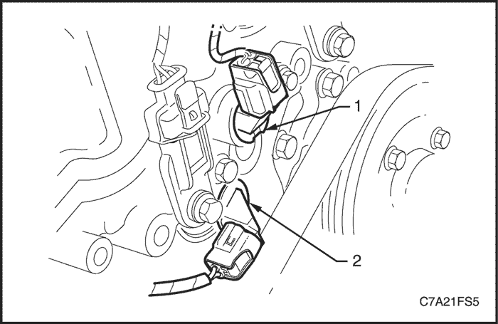
Camshaft Position Actuator Solenoid
Removal Procedure
Bank 1
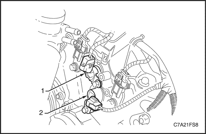
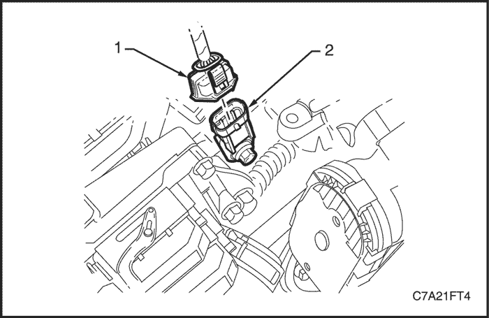
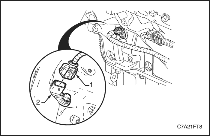
Note : The replacement procedure for the intake (1) and exhaust (2) camshaft position (CMP) actuator solenoids are typically the same, with the following procedure being specific to the intake CMP actuator solenoid.
- Disconnect the negative battery cable.
- Remove the air cleaner assembly. Refer to Section 1C2, Engine Mechanical - HFV6 3.2L.
- Remove the engine mount support bracket. Refer to Section 1C2, Engine Mechanical - HFV6 3.2L.
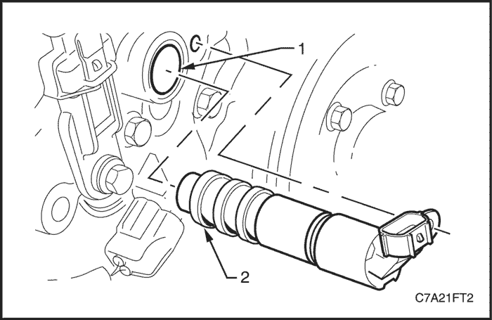
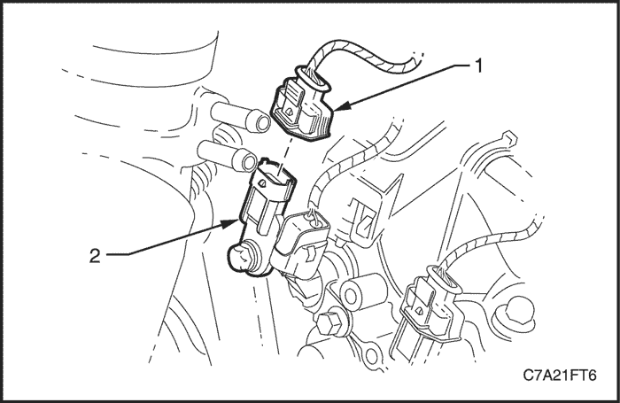
- Disconnect the wiring harness connector (1) from the CMP actuator solenoid (2).
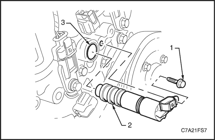
Caution : Clean the area around the CMP actuator solenoid before removal to avoid debris from entering the engine.
- Remove the bolt (1) attaching the CMP actuator solenoid (2).
Caution : When removing the CMP actuator solenoid, care must be taken to prevent the annular grooves of the actuator from damaging the CMP actuator solenoid seal (3).
- Remove the CMP actuator solenoid by first twisting the actuator to release it, and then pulling it away from the front engine cover to remove it.
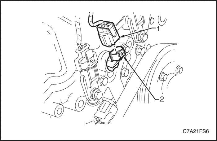
Bank 2
Note : The replacement procedure for the intake (1) and exhaust (2) camshaft position (CMP) actuator solenoids are typically the same, with the following procedure being specific to the intake CMP actuator solenoid. Where there are differences in the removal procedures, these will be highlighted.
- Disconnect the negative battery cable.
- Remove the air cleaner assembly. Refer to Section 1C2, Engine Mechanical - HFV6 3.2L.
- Remove the engine mount support bracket. Refer to Section 1C2, Engine Mechanical - HFV6 3.2L.
- If removing the exhaust CMP actuator solenoid, remove the accessory drive belt. Refer to Section 1C2, Engine Mechanical - HFV6 3.2L.
- Disconnect the wiring harness connector (1) from the CMP actuator solenoid (2).
Caution : Clean the area around the CMP actuator solenoid before removal to avoid debris from entering the engine.
- Remove the bolt (1) attaching the CMP actuator solenoid (2).
Caution : When removing the CMP actuator solenoid, care must be taken to prevent the annular grooves of the actuator from damaging the CMP actuator solenoid seal (3).
- Remove the CMP actuator solenoid by first twisting the actuator to release it, and then pulling it away from the front engine cover to remove it.
Installation Procedure
Bank 1
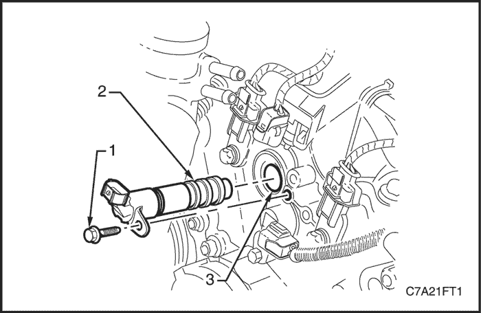
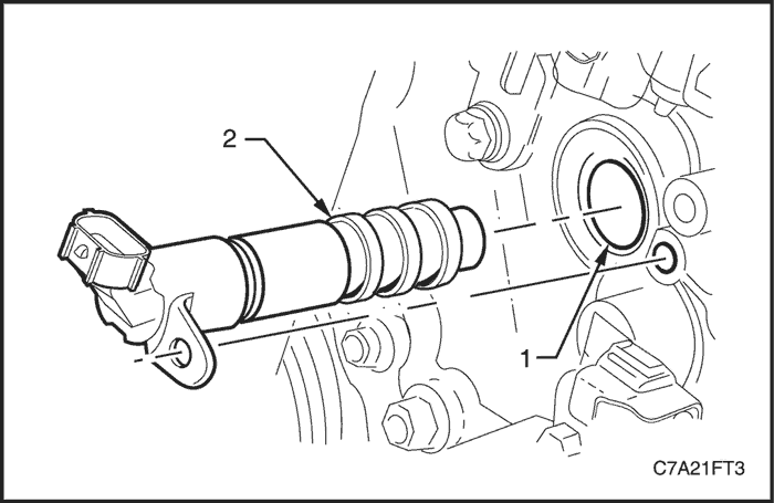
- Inspect the CMP actuator solenoid seal (1) for damage, and replace if necessary.
- Lubricate the lip of the CMP actuator solenoid seal with clean engine oil.
Caution : When installing the CMP actuator solenoid, care must be taken to prevent the annular grooves (2) of the actuator from damaging the CMP actuator solenoid seal.
- Install the CMP actuator solenoid.
Tighten
Tighten the camshaft position actuator solenoid attaching bolt to 10 N•m (89 lb-in).
Bank 2
- Inspect the CMP actuator solenoid seal (1) for damage, and replace if necessary.
- Lubricate the lip of the CMP actuator solenoid seal with clean engine oil.
Caution : When installing the CMP actuator solenoid, care must be taken to prevent the annular grooves (2) of the actuator from damaging the CMP actuator solenoid seal.
- Install the CMP actuator solenoid.
Tighten
Tighten the camshaft position actuator solenoid attaching bolt to 10 N•m (89 lb-in).
Camshaft Position Sensor
Removal Procedure
Note : The replacement procedure for the intake and exhaust camshaft position (CMP) sensors are typically the same, with the following procedure being specific to the intake CMP sensor.
Bank 1
- Disconnect the negative battery cable.
- Remove the air cleaner assembly. Refer to Section 1C2, Engine Mechanical - HFV6 3.2L.
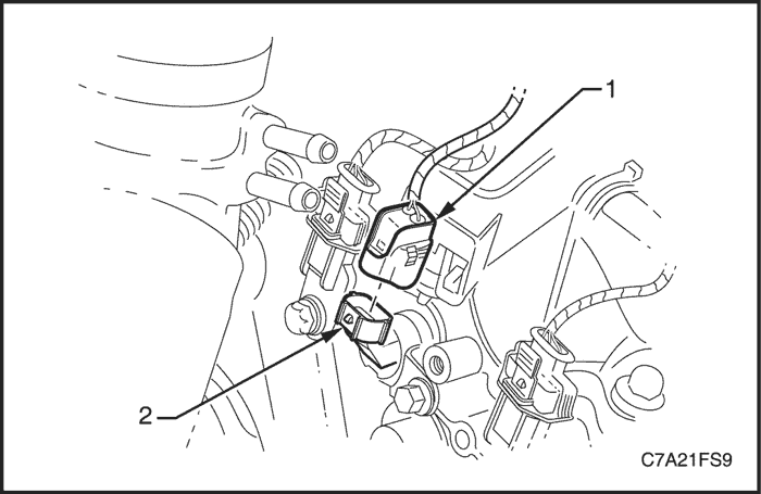
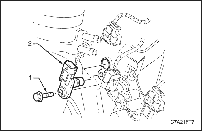
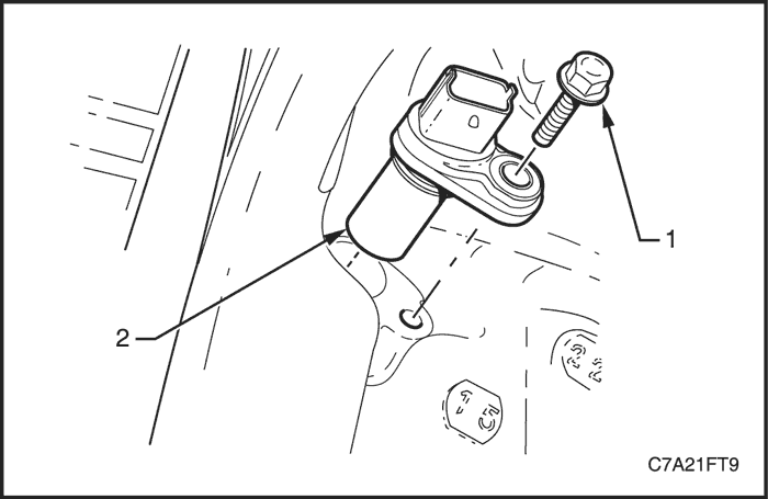
- Disconnect the wiring harness connector (1) from the CMP sensor (2).
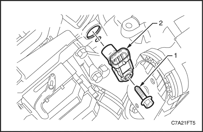
Caution : Clean the area around the CMP sensor before removal to avoid debris from entering the engine.
- Remove the CMP sensor attaching bolt (1).
- Remove the CMP sensor (2) by first twisting the sensor to release it, and then pulling it away from the front engine cover to remove it.
Bank 2
- Disconnect the negative battery cable.
- Remove the air cleaner assembly. Refer to Section 1C2, Engine Mechanical - HFV6 3.2L.
- Disconnect the wiring harness connector (1) from the CMP sensor (2).
Caution : Clean the area around the CMP sensor before removal to avoid debris from entering the engine.
- Remove the CMP sensor attaching bolt (1).
- Remove the CMP sensor (2) by first twisting the sensor to release it, and then pulling it away from the front engine cover to remove it.
Installation Procedure
Bank 1
- Lubricate the CMP sensor O-ring with clean engine oil.
- Install the CMP sensor (2) by pushing in on the sensor to engage the sensor O-ring in the front engine cover.
Caution : Ensure the CMP sensor is fully seated before tightening the attaching bolt to the specified torque.
- Install the CMP sensor attaching bolt (1).
Tighten
Tighten the camshaft position sensor attaching bolt to 10 N•m (89 lb-in).
- Connect the CMP sensor connector.
Bank 2
- Lubricate the CMP sensor O-ring with clean engine oil.
- Install the CMP sensor (2) by pushing down on the sensor to engage the sensor O-ring in the front engine cover.
Caution : Ensure the CMP sensor is fully seated before tightening the attaching bolt to the specified torque.
- Install the CMP sensor attaching bolt (1).
Tighten
Tighten the camshaft position sensor attaching bolt to 10 N•m (89 lb-in).
- Connect the CMP sensor connector.
Crankshaft Position Sensor
Removal Procedure
- Disconnect the negative battery cable.
- Remove the exhaust front pipe. Refer to Section 1G3, Engine Exhaust - HFV6 3.2L.
- Remove the transfer case. Refer to Section 5D, Transfer Case.
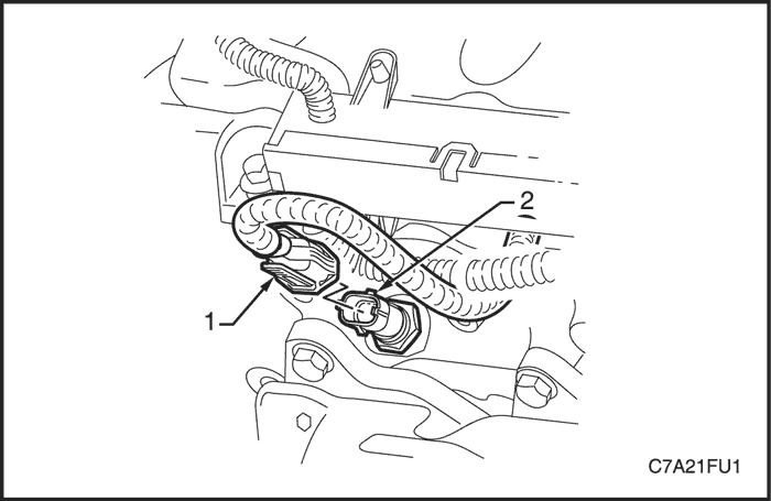
- Disconnect the wiring harness connector (1) from the crankshaft position (CKP) sensor (2).
Caution : Clean the area around the CKP sensor before removal to avoid debris from entering the engine.
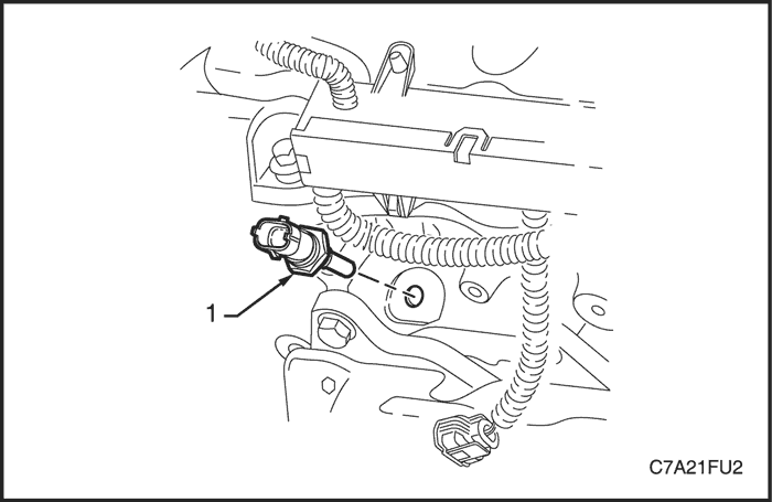
- Remove the CKP sensor attaching bolt (1).
- Remove the CKP sensor (2), by first twisting the sensor to release it, and then pulling it away from the engine block to remove it.
Installation Procedure
- Lubricate the CKP sensor O-ring with clean engine oil.
- Reinstall the CKP sensor by pushing down on the sensor to engage the sensor O-ring in the engine block.
Caution : Ensure the CKP sensor is fully seated before tightening the attaching bolt to the specified torque.
- Install the CKP sensor attaching bolt.
Tighten
Tighten the crankshaft position sensor attaching bolt to 10 N•m (89 lb-in).
- Connect the CKP sensor connector.
Engine Coolant Temperature Sensor
Removal Procedure
Caution : To avoid serious personal injury, never remove the engine coolant temperature (ECT) sensor when the engine is hot. Allow the engine to cool to ambient temperature (less than 50(C) before performing this procedure.
- Disconnect the negative battery cable.
- Remove the engine dress cover. Refer to Section 1C2, Engine Mechanical - HFV6 3.2L.
Caution : To avoid serious personal injury, never remove the coolant filler cap when the engine is hot. Allow the engine to cool to ambient temperature (less than 50°C) before performing this procedure.
- Allow the engine to cool to ambient temperature less than 50°C, and slowly remove coolant filler cap.
- Drain approximately two liters of coolant into a suitable container.
- Disconnect the wiring harness connector (1) from the ECT sensor (2).
Caution : Clean the area around the ECT before removal to avoid debris from entering the engine.
- Remove the ECT sensor (1).
Note : If coolant leaks from the cylinder head as the sensor is removed, screw the sensor back into the cylinder head and drain more coolant from the cooling system.
Installation Procedure
- Install the ECT sensor.
Tighten
Tighten the engine coolant temperature sensor to 22 N•m (16 lb-ft).
- Connect the ECT sensor connector.
- Refill the cooling system. Refer to Section 1D3, Engine Cooling - HFV6 3.2L.
Engine Oil Pressure Sensor
Removal Procedure
Caution : To avoid personal injury, take care when removing the engine oil pressure sensor when the engine is hot. Allow the engine to cool before performing this procedure.
- Disconnect the negative battery cable.
- Remove the engine dress cover. Refer to Section 1C2, Engine Mechanical - HFV6 3.2L.
- Drain the engine oil by removing the engine oil drain plug.
- Disconnect the wiring harness connector from the engine oil pressure sensor.
Caution : Clean the area around the engine oil pressure sensor before removal to avoid debris from entering the engine.
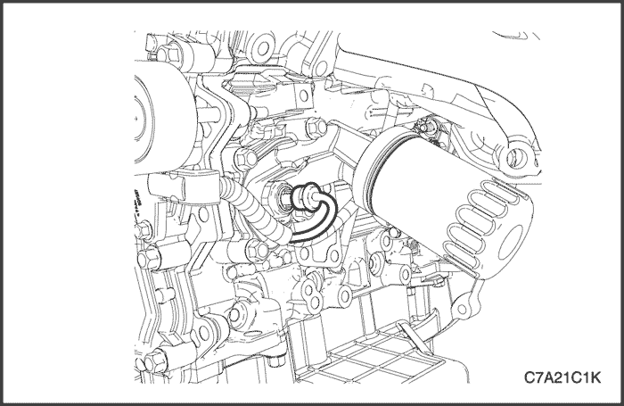
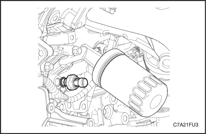
- Remove the engine oil pressure sensor.
Installation Procedure
- Install the oil pressure sensor.
Tighten
Tighten the engine oil pressure sensor to 13 N•m (115 lb-in).
- Connect the engine oil pressure sensor connector.
Evaporative Emission Canister Purge Valve
Removal Procedure
- Disconnect the negative battery cable.
- Remove the engine dress cover. Refer to Section 1C2, Engine Mechanical - HFV6 3.2L.
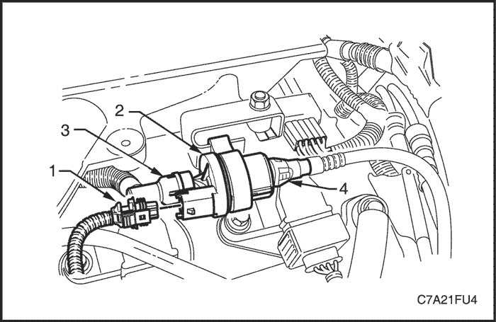
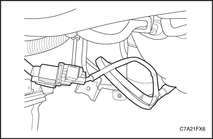
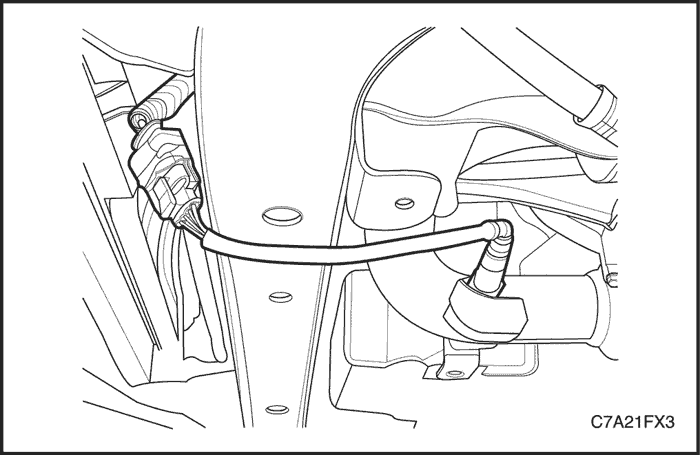
- Disconnect the wiring harness connector (1) from the evaporative emission (EVAP) canister purge valve (2).
- Disconnect the two EVAP canister purge valve hoses (3 and 4).
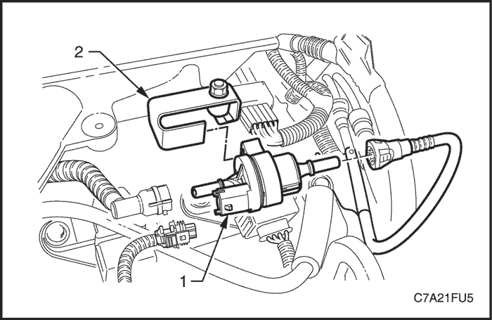
- Slide the EVAP canister purge valve (1) from the purge valve mounting bracket (2).
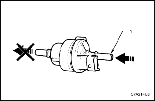
- If required, perform the function test of the EVAP canister purge valve as follows :
- Attempt to blow air through the EVAP canister purge valve inlet port (1). If air passes through the valve, the valve is faulty and should be replaced.
Installation Procedure
- Slide the EVAP canister purge valve to the purge valve mounting bracket.
- Connect the two EVAP canister purge valve hoses (3 and 4).
- Connect the wiring harness connector (1) to the EVAP canister purge valve (2).
Evaporative (EVAP) Emission Canister Assembly
Removal Procedure
Caution : Canister and vacuum hoses contain the fuel vapors. Do not smoke in the area or permit an open flame.
- Disconnect the canister fuel vapor hoses from the canister.
- Loosen the clamp and disconnect the evaporative (EVAP) emission canister vent hose from the EVAP emission canister filter.
- Remove the EVAP emission canister bracket retaining nuts and the EVAP emission canister assembly.
- Separate the canister from the EVAP emission canister bracket.
- Remove the canister.
Installation Procedure
- Install the EVAP emission canister onto the EVAP emission canister bracket.
- Install the EVAP emission canister assembly.
Tighten
Tighten the evaporative emission canister bracket retaining nuts to 10 N•m (89 lb-in).
- Connect the EVAP emission canister vent hose to the EVAP emission canister filter.
- Connect the canister fuel vapor hoses to the canister.
Evaporative (EVAP) Emission Canister Filter
Removal Procedure
- Remove the EVAP emission canister assembly. Refer to "Evaporative Emission Canister Assembly" in this section.
- Loosen the clamp and disconnect the EVAP emission canister vent hose from the EVAP emission canister filter.
- Remove the EVAP canister emission canister filter by unclipping the clips from the EVAP emission canister bracket.
Installation Procedure
- Install the EVAP emission canister filter to the EVAP emission canister bracket.
- Connect the EVAP emission canister vent hose to the EVAP emission canister filter.
- Install the EVAP emission canister assembly. Refer to "Evaporative Emission Canister Assembly" in this section.
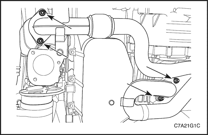
Evaporative (EVAP) Emission Pipe Assembly
Removal Procedure
- Disconnect the negative battery cable.
- Disconnect the EVAP emission canister purge front hose from the EVAP emission canister purge solenoid valve.
- Disconnect the EVAP emission canister purge front hose from the EVAP emission pipe.
- Disconnect the EVAP emission pipe rear hose from the EVAP emission canister.
- Remove the EVAP emission canister vapor pipe protector bracket.
- Remove the EVAP emission canister vapor pipe retaining clips.
- Remove the EVAP emission canister vapor pipe.
Installation Procedure
- Install the EVAP emission canister vapor pipe with the retaining clips.
- Install the EVAP emission canister vapor pipe retaining clips.
- Install the EVAP emission canister vapor pipe protector bracket.
- Connect the EVAP emission pipe rear hose to the EVAP emission canister.
- Connect the EVAP emission canister purge front hose to the EVAP emission canister pipe.
- Connect the EVAP emission canister purge front hose to the EVAP emission canister purge solenoid valve.
Heated Oxygen Sensor
Removal Procedure
Bank 1 - Sensor 1
- Disconnect the negative battery cable.
Notice : The oxygen sensor used a permanently attached pigtail and connector. This pigtail should not be removed from the oxygen sensor. Damage or removal of the pigtail or the connector affect the proper operation of the oxygen sensor. Take care when handing the oxygen sensor. Do not drop the oxygen sensor.
- Disconnect the upper heated oxygen sensor connector at the back of the Bank 1 cylinder head.
- Remove the exhaust front pipe. Refer to Section 1G3, Engine Exhaust - HFV6 3.2L.
- Remove the rear pup converter. Refer to Section 1G3, Engine Exhaust - HFV6 3.2L.
- Remove the rear exhaust manifold. Refer to Section 1C2, Engine Mechanical - HFV6 3.2L.
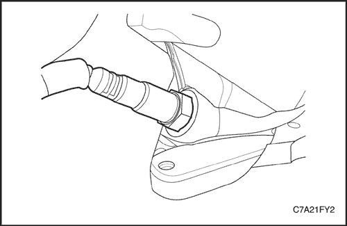
Caution : Allow the engine to cool before removing the oxygen sensor. Removal of the oxygen sensor when the engine is hot may damage the threads in the exhaust manifold.
- Using the oxygen sensor remover/installer DW170-010, carefully remove the upper heated oxygen sensor from the rear exhaust manifold.
Bank 1 - Sensor 2
- Disconnect the negative battery cable.
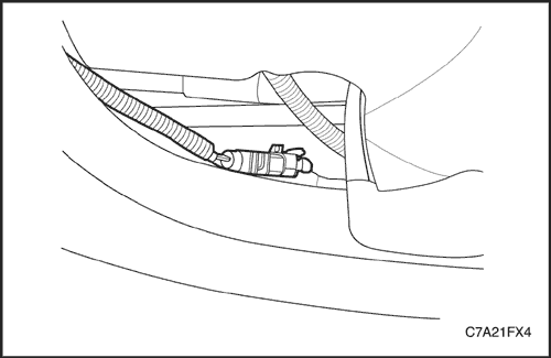
- Disconnect the lower heated oxygen sensor connector.
Caution : Allow the engine to cool before removing the oxygen sensor. Removal of the oxygen sensor when the engine is hot may damage the threads in the exhaust manifold.
- Using the oxygen sensor remover/installer DW170-010, carefully remove the lower heated oxygen sensor from the exhaust front pipe.
Bank 2 - Sensor 1
- Disconnect the negative battery cable.
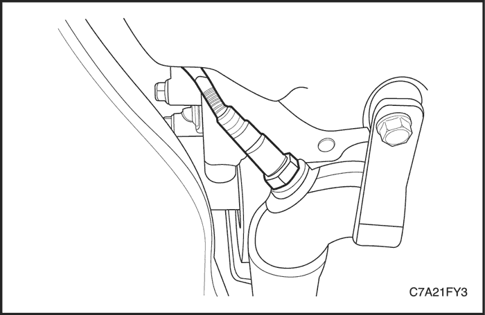
- Disconnect the upper heated oxygen sensor connector.
Caution : Allow the engine to cool before removing the oxygen sensor. Removal of the oxygen sensor when the engine is hot may damage the threads in the exhaust manifold.
- Using the oxygen sensor remover/installer DW170-010, carefully remove the upper heated oxygen sensor from the front exhaust manifold.
Bank 2 - Sensor 2
- Disconnect the negative battery cable.
- Disconnect the lower heated oxygen sensor connector.
Caution : Allow the engine to cool before removing the oxygen sensor. Removal of the oxygen sensor when the engine is hot may damage the threads in the exhaust manifold.
- Remove the lower heated oxygen sensor from the exhaust front pipe.
Installation Procedure
Important : A special anti-seize compound is used on the oxygen sensor threads. This compound consists of a liquid graphite and glass beads. The graphite will burn away, but the glass beads will remain, making the sensor easier to remove. New or serviced sensors will already have the compound applied to the threads. If a sensor is removed from any engine and is to be reinstalled, the threads must have an anti-seize compound applied before reinstallation.
Bank 1 - Sensor 1
- Coat the threads of the oxygen sensor with anti-seize compound, if needed.
- Using the oxygen sensor remover/installer DW170-010, install the upper heated oxygen sensor to the rear exhaust manifold. This pigtail should not be removed from the oxygen sensor. Damage or removal of the pigtail or the connector affect the proper operation of the oxygen sensor. Take care when handing the oxygen sensor. Do not drop the oxygen sensor.
Tighten
Tighten the heated oxygen sensor to 50 N•m (37 lb-ft).
Bank 1 - Sensor 2
- Coat the threads of the oxygen sensor with anti-seize compound, if needed.
- Using the oxygen sensor remover/installer DW170-010, install the lower heated oxygen sensor to the exhaust front pipe.
Tighten
Tighten the heated oxygen sensor to 50 N•m (37 lb-ft).
- Connect the upper heated oxygen sensor connector.
- Connect the negative battery cable.
Bank 2 - Sensor 1
- Coat the threads of the oxygen sensor with anti-seize compound, if needed.
- Using the oxygen sensor remover/installer DW170-010, install the upper heated oxygen sensor to the front exhaust manifold.
Tighten
Tighten the heated oxygen sensor to 50 N•m (37 lb-ft).
- Connect the upper heated oxygen sensor connector.
- Connect the negative battery cable.
Bank 2 - Sensor 2
- Coat the threads of the oxygen sensor with anti-seize compound, if needed.
- Using the oxygen sensor remover/installer DW170-010, install the lower heated oxygen sensor to the exhaust front pipe.
Tighten
Tighten the heated oxygen sensor to 50 N•m (37 lb-ft).
- Connect the lower heated oxygen sensor connector.
- Connect the negative battery cable.
Accelerator Pedal Module (APM)
Removal Procedure
- Disconnect the negative battery cable.
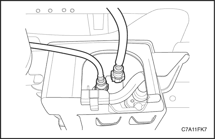
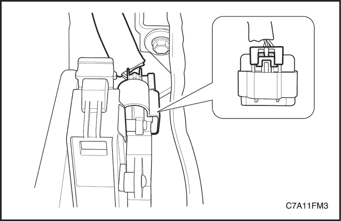
- Disconnect the accelerator pedal module (APM) connector locking tab from the APM connector.
- Disconnect the APM connector.
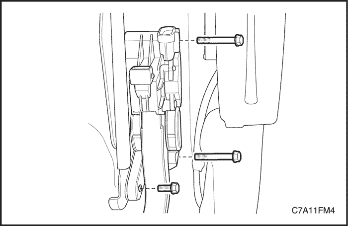
- Remove the bolts, three places, attaching the APM from the accelerator and brake pedal module bracket.
Installation Procedure
- Install the APM retaining bolts to the accelerator and brake pedal module bracket.
Tighten
Tighten the accelerator pedal module retaining bolts to 9 N•m (80 lb-in).
- Connect the APM connector and the install the locking tab firmly.
Engine Control Module
Removal Procedure
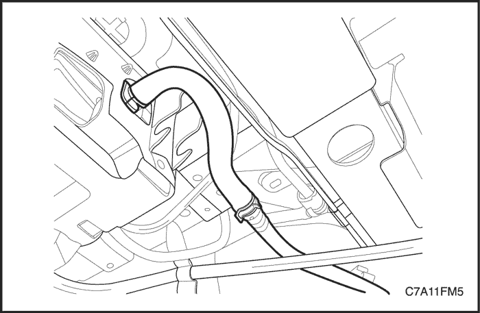
- Disconnect the positive crankcase ventilation (PCV) hose from the air intake duct.
- Loosen the clamps and remove the air intake duct from the mass air flow sensor assembly and the throttle body.
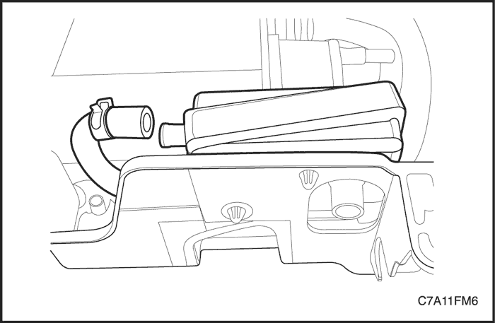
- Disconnect the engine control module (ECM) connector.
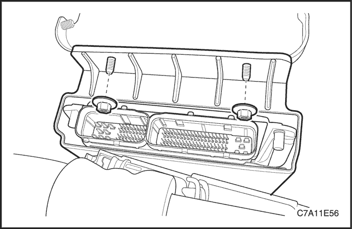
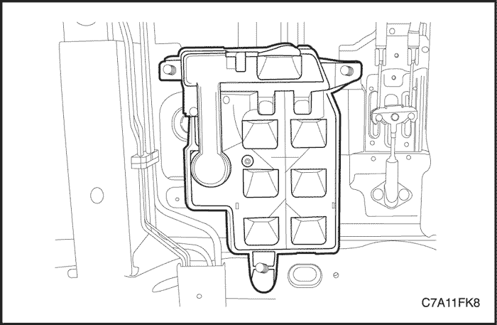
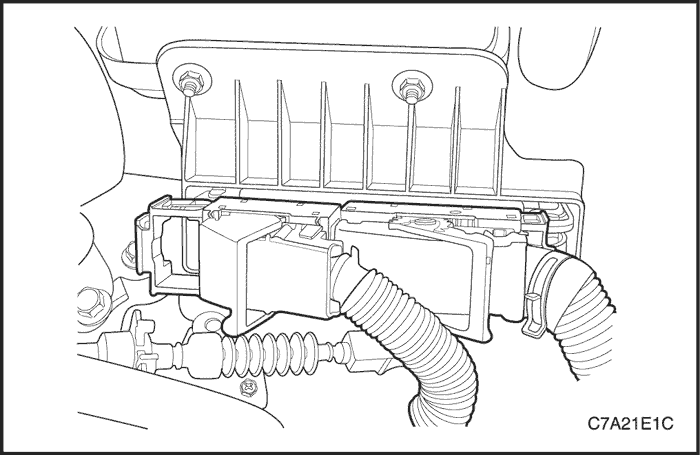
- Remove the ECM bracket retaining nuts.
- Remove the ECM with the bracket attached from the battery tray.
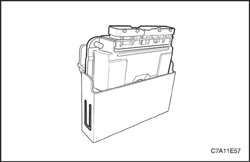
- Unclip the ECM to the bracket and separate the ECM from the bracket.
Installation Procedure
- Install the ECM into the bracket.
- Install the ECM with the bracket attached to the battery tray.
Tighten
Tighten the engine control module bracket retaining nuts to 15 N•m (11 lb-ft).
- Connect the ECM connectors.
- Connect the negative battery cable.
Caution : If the ECM has been replaced, perform the ECM reprogramming and the oil remaining life reset process.
| © Copyright Chevrolet Europe. All rights reserved |


