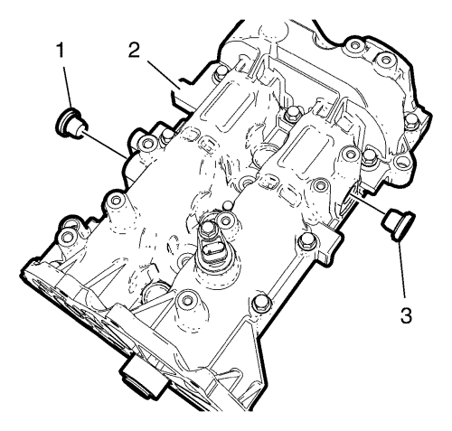
- Install the 2EN-50515 fixing tools (1) on exhaust and intake side.
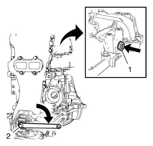
Note: Engage the EN-50515 fixing tool at the intake camshaft
- Apply pressure at EN-50515 fixing tool (arrow) and carefully turn the crankshaft at the crankshaft sprocket bolt (2) in the direction of engine rotation (arrow), until EN-50515 fixing tool (1) engages in the intake camshaft.
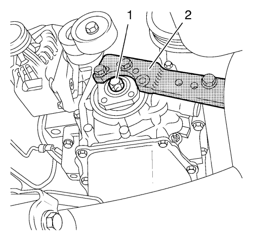
- Install EN-662-C holding wrench (2) to counterhold the crankshaft.
- Install 2 bolts.
- Loosen the crankshaft sprocket bolt (1)
Note: Counterhold at the camshaft sprocket. Second person required.
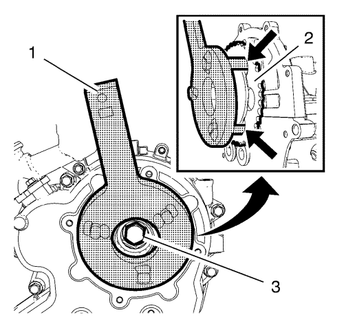
Note: The holding pins from the EN-50514 holder (1) must be installed exactly in the holes (arrows) from the camshaft sprocket (2).
- Install EN-50514 holder (1) with the EN-956-1 extension to counterhold the camshaft sprocket (2).
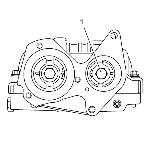
- Loosen the camshaft intake sprocket bolt (1).
- Rotate the exhaust camshaft 15° against the direction of engine rotation.
- Turn the exhaust camshaft at the camshaft sprocket bolt in direction of the engine rotation until the EN-50515 fixing tool engages in the exhaust camshaft.
- Remove and DISCARD the camshaft intake sprocket bolt (1).
- Install the NEW camshaft intake sprocket bolt (1).
Caution: Refer to Fastener Caution in the Preface section.
Caution: Refer to Torque-to-Yield Fastener Caution in the Preface section.
Note: Counterhold the camshaft sprocket withEN-50514 holder .
- Tighten the NEW camshaft intake sprocket bolt (1) to 100 N·m +45° (74 lb ft +45°).
- Counterhold crankshaft with EN-662-C holding wrench (2).
- Tighten the crankshaft sprocket bolt (1) to 50 N·m +90° (37 lb ft +90°).
Note: The holding pins from the EN-50514 holder (1) must be installed exactly in the holes (arrows) from the camshaft sprocket (2).
- Install EN-50514 holder (1) with the EN-956-1 extension to counterhold the camshaft sprocket (2).
Note: Do not remove the camshaft sprocket bolt (3).
- Loosen the camshaft sprocket bolt (3).
- Remove the EN-50514 holder (1).
Note: If the transmission is installed.
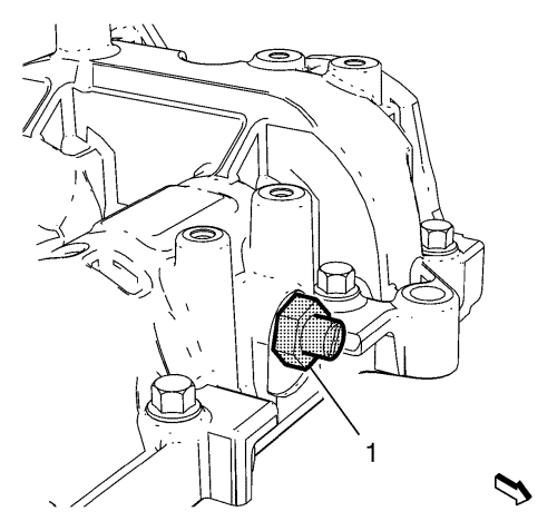
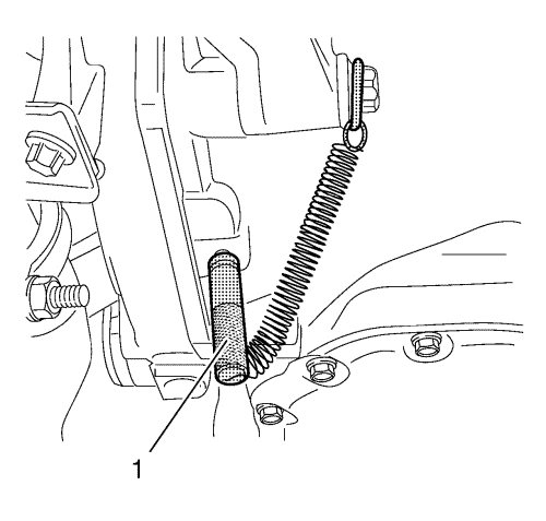
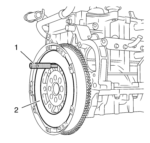
- Carefully turn the crankshaft until the EN-46785 fixing tool (1) engages in the flywheel.
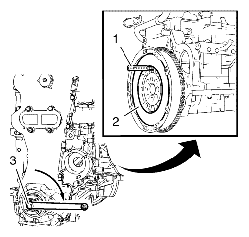
Note: If the transmission is removed.
- Carefully turn the crankshaft until the EN-50516 fixing tool (1) engages in the flywheel and the engine block.
- Remove and DISCARD the camshaft sprocket bolt (3).
- Install the NEW camshaft sprocket bolt (3).
Note: The holding pins from the EN-50514 holder (1) must be installed exactly in the holes (arrows) from the camshaft sprocket (2).
- Install EN-50514 holder (1) with the EN-956-1 extension to counterhold the camshaft sprocket (2).
Caution: Refer to Torque-to-Yield Fastener Caution in the Preface section.
- Tighten the NEW camshaft sprocket bolt (3) to 100 N·m +45° (74 lb ft +45°).
- Remove the EN-50514 holder (1).
- Loosen the crankshaft sprocket bolt (1).
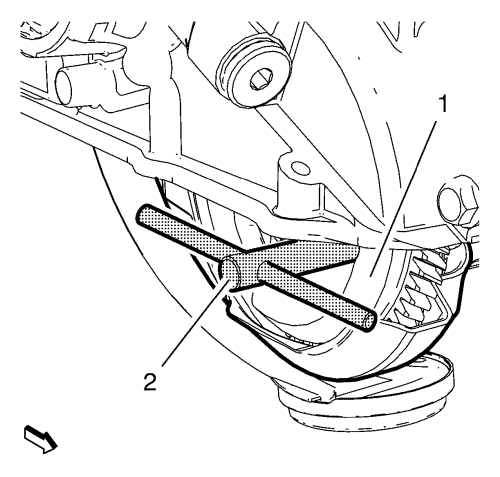
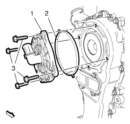
- Install EN-50519 fixing tool (2) to balance shaft driven gear (1).
- Counterhold crankshaft with EN-662-C holding wrench (2).
- Remove and DISCARD the crankshaft sprocket bolt (1).
- Install the NEW crankshaft sprocket bolt (1).
Caution: Refer to Fastener Caution in the Preface section.
Caution: Refer to Torque-to-Yield Fastener Caution in the Preface section.
- Tighten the NEW crankshaft sprocket bolt (1) to 50 N·m +90° (37 lb ft +90°).
- Remove the EN-50519 fixing tool (2) from the balance shaft driven gear (1).
- Remove the 2 EN-50515 fixing tools (1).
Note: If the transmission is installed.
- Remove the EN-46785 fixing tool (1).
Note: If the transmission is removed.
- Remove the EN-50516 fixing tool (1).
- Inspect the camshaft timing chain. Refer to Camshaft Timing Chain Inspection .