Captiva
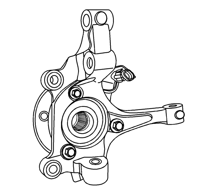
Steering Knuckle Replacement
Removal Procedure
Raise and support the vehicle on an alignment rack. Refer to
Lifting and Jacking the Vehicle
.
Remove the front tyre and wheel assembly. Refer to
Tyre and Wheel Removal and Installation
.
Remove the front brake rotor. Refer to
Front Brake Disc Replacement
.
Remove the wheel speed sensor electrical connector, if equipped, from the connector bracket. Refer to
Front Wheel Speed Sensor Replacement
.
Separate the wheel drive shaft from the knuckle. Refer to
Front Wheel Drive Shaft Replacement
.
Remove the outer tie rod end from the knuckle. Refer to
Steering Linkage Outer Tie Rod Inspection
.
Remove the control arm ball joint from the knuckle. Refer to
Lower Control Arm Replacement
.
Support the wheel drive shaft with heavy mechanic's wire or equivalent.
Remove the front strut to knuckle nuts and bolts. Refer to
Strut Assembly Removal and Installation
.
Remove the knuckle assembly from the wheel drive shaft.
Remove front wheel bearing and hub assembly from the knuckle, if needed. Refer to
Front Wheel Bearing and Hub Replacement
.
Installation Procedure
Install front wheel bearing and hub assembly in the knuckle, if needed. Refer to
Front Wheel Bearing and Hub Replacement
.
Position the wheel drive shaft in the knuckle.
Remove the mechanic's wire from the wheel drive shaft.
Install the front strut to knuckle nuts and bolts. Refer to
Strut Assembly Removal and Installation
.
Install the control arm ball joint in the knuckle. Refer to
Lower Control Arm Replacement
.
Install the outer tie rod end in the knuckle. Refer to
Steering Linkage Outer Tie Rod Inspection
.
Install the front brake rotor. Refer to
Front Brake Disc Replacement
.
Install the wheel drive shaft nut to the wheel drive shaft. Refer to
Front Wheel Drive Shaft Replacement
.
Install the wheel speed sensor electrical connector, if equipped, to the connector bracket. Refer to
Front Wheel Speed Sensor Replacement
.
Install the front tyre and wheel assembly. Refer to
Tyre and Wheel Removal and Installation
.
Measure the wheel alignment. Adjust the wheel alignment if necessary. Refer to
Wheel Alignment Specifications
.
Lower the vehicle.
© Copyright Chevrolet. All rights reserved