Engine Front Cover Replacement
Special Tools
EN-46109 Engine Front Cover Installation Guide Pins
For equivalent regional tools, refer to Special Tools .
Removal Procedure
- Remove the intake manifold. Refer to Inlet Manifold Replacement .
- Remove the camshaft covers. Refer to Camshaft Cover Replacement - Left Side and Camshaft Cover Replacement - Right Side .
- Drain the engine coolant. Refer to Cooling System Draining and Filling .
- Disconnect the purge vent hose from the water outlet.
- Remove the water outlet with the radiator hose and reposition aside. Refer to
Water Outlet Replacement : LF1 .
- Remove the crankshaft balancer. Refer to Crankshaft Balancer Replacement .
- Remove the camshaft position sensors. Refer to Camshaft Position Sensor Replacement - Bank 2 (Left Side) Exhaust , Camshaft Position Sensor Replacement - Bank 2 (Left Side) Intake , Camshaft Position Sensor Replacement - Bank 1 (Right Side) Exhaust and Camshaft Position Sensor Replacement - Bank 1 (Right Side) Intake .
- Remove the generator. Refer to
Generator Replacement : LNQ → LF1 → LE5 .
- Remove the water pump pulley only.
- Remove the drive belt tensioner. Refer to Drive Belt Tensioner Replacement .
- Remove the camshaft position actuator solenoid valves from the front cover. Refer to Camshaft Position Actuator Solenoid Valve Solenoid Replacement - Bank 1 (Right Side) Intake , Camshaft Position Actuator Solenoid Valve Solenoid Replacement - Bank 1 (Right Side) Exhaust , Camshaft Position Actuator Solenoid Valve Solenoid Replacement - Bank 2 (Left Side) Intake , and Camshaft Position Actuator Solenoid Valve Solenoid Replacement - Bank 2 (Left Side) Exhaust .
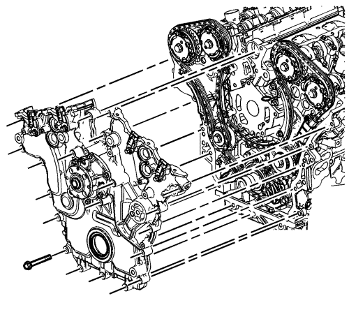
Note: There are a total of 22 M8 bolts that must be removed and 3 optional M12 bolts that may need to be removed before the front cover will separate from the engine block.
- Remove the engine front cover with the water pump. Refer to Engine Front Cover Removal .
- Disassemble the engine front cover. Refer to Engine Front Cover Disassemble .
Note: Do NOT use sharp and/or metal gasket scrapers in order to clean the sealing surfaces.
- Carefully clean the engine front cover sealing surfaces. Refer to Engine Front Cover Cleaning and Inspection .
Note: Insert a piece of cardboard between the sump front and the oil pump in order to prevent any contaminants from falling into the sump.
- Carefully clean the engine front cover sealing surfaces. Refer to Engine Front Cover Cleaning and Inspection .
- Use compressed air in order to remove any engine coolant from the engine cooling passages and from the top of the sump scraper (windage tray).
Installation Procedure
- Assemble the engine front cover. Refer to Engine Front Cover Assemble .
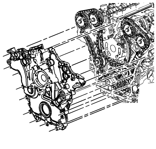
- Use the EN-46109 pins in order to install the engine front cover. Refer to Engine Front Cover Installation .
- Install the camshaft position actuator solenoid valves to the front cover. Refer to Camshaft Position Actuator Solenoid Valve Solenoid Replacement - Bank 1 (Right Side) Intake , Camshaft Position Actuator Solenoid Valve Solenoid Replacement - Bank 1 (Right Side) Exhaust , Camshaft Position Actuator Solenoid Valve Solenoid Replacement - Bank 2 (Left Side) Intake , and Camshaft Position Actuator Solenoid Valve Solenoid Replacement - Bank 2 (Left Side) Exhaust .
- Install the camshaft position sensors. Refer to Camshaft Position Sensor Replacement - Bank 2 (Left Side) Exhaust , Camshaft Position Sensor Replacement - Bank 2 (Left Side) Intake , Camshaft Position Sensor Replacement - Bank 1 (Right Side) Exhaust and Camshaft Position Sensor Replacement - Bank 1 (Right Side) Intake .
- Install the crankshaft balancer. Refer to Crankshaft Balancer Installation .
- Install the alternator bracket with the alternator and the belt tensioner. Refer to
Generator Replacement : LNQ → LF1 → LE5 .
- Install the water outlet. Refer to
Water Outlet Replacement : LF1 .
- Install the purge vent hose to the water outlet.
- Fill the cooling system. Refer to Cooling System Draining and Filling .
- Install the water pump pulley.
- Install the drive belt tensioner. Refer to Drive Belt Tensioner Replacement .
- Install the camshaft covers. Refer to Camshaft Cover Replacement - Left Side and Camshaft Cover Replacement - Right Side .
- Install the inlet manifold. Refer to Inlet Manifold Replacement .
- Fill the cooling system. Refer to Cooling System Draining and Filling .
| © Copyright Chevrolet. All rights reserved |


