To the top of the document
Cruze
   
GMDE Start Page Load static TOC Load dynamic TOC Help?

Cylinder Head Replacement

Special Tools

    • GE-571-B Dial Gauge
    • EN-45059 Angle Meter

For equivalent regional tools, refer to Special Tools .

Removal Procedure

  1. Remove the air cleaner outlet front duct. Refer to Air Cleaner Outlet Front Duct Replacement .
  2. Remove the catalytic converter. Refer to Catalytic Converter Replacement : 1.4L LUH and LUJ → 1.6L LXT,L2W → 1.6L LDE, LXV, 1.8L 2H0, and LUW → 2.0L Diesel LLW .
  3. Remove the turbocharger oil feed pipe. Refer to Turbocharger Oil Feed Pipe Replacement .
  4. Remove the turbocharger oil return pipe. Refer to Turbocharger Oil Return Pipe Replacement .
  5. Remove the camshaft cover. Refer to Camshaft Cover Replacement .
  6. Remove the timing belt. Refer to Timing Belt Replacement .
  7. Remove oil level indicator tube. Refer to Oil Level Indicator and Tube Removal .

  8. 2028263
  9. Remove the coolant temperature sensor wiring harness plug (1).
  10. Remove inlet air pressure and temperature sensor wiring harness plug (3).
  11. Remove the wiring harness (2).
  12. Remove radiator inlet hose clamp (6).
  13. Remove the radiator inlet hose (7).
  14. Remove the fuel hose -- fuel injection pump to fuel feed block. Refer to Fuel Hose Replacement - Fuel Injection Pump to Fuel Feed Block .

  15. 2027084
  16. Remove the wiring harness plug (2) from electronic throttle actuator control module (1).

  17. 2028279
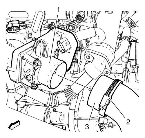
  18. Loosen the charge air cooler outlet air hose clamp.
  19. Remove the charge air cooler outlet hose (3) from the throttle body (1).

  20. 2027737
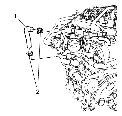
  21. Remove the 2 hose clamps (2).
  22. Remove the EGR manifold cooling return hose (1).

  23. 2027736
  24. Remove the 2 hose clamps (1).
  25. Remove the EGR manifold cooling feed hose (2).

  26. 2028272
  27. Remove the charge air cooler inlet hose clamp (3).
  28. Remove the charge air cooler inlet hose (2) from the turbocharger (1).

  29. 2027917
  30. Loosen the 10 cylinder head bolts as shown in the graphic.

  31. 2027915
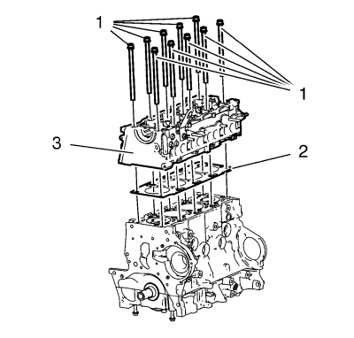
  32. Remove and DISCARD the 10 cylinder head bolts (1).
  33. Remove the cylinder head (3).
  34. Remove the cylinder head gasket (2).

Disassemble Procedure

  1. Remove the exhaust gas recirculation valve pipe. Refer to Exhaust Gas Recirculation Valve Pipe Removal .
  2. Remove the exhaust gas recirculation pipe. Refer to Exhaust Gas Recirculation Pipe Removal .
  3. Remove the exhaust gas recirculation valve cooler. Refer to Exhaust Gas Recirculation Valve Cooler Removal .
  4. Remove the intake manifold. Refer to Inlet Manifold Removal .
  5. Remove the exhaust manifold. Refer to Exhaust Manifold Removal .
  6. Remove the glow plug. Refer to Glow Plug Removal .
  7. Remove the camshaft. Refer to Camshaft Removal .

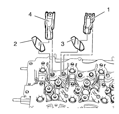
  8. 2027905
  9. Remove the 8 valve rocker arms (4, 1).
  10. Remove the 8 tappet bridges (2, 3)
  11. Remove the 16 valves. Refer to Cylinder Head Disassemble .

Cleaning Procedure

  1. Clean the cylinder head surface.
  2. Clean the engine block surface.
  3. Clean the engine block bolt holes.

Assemble Procedure

  1. Install the 16 valves. Refer to Cylinder Head Assemble .

  2. 2027905
  3. Install the 8 tappet bridges (2, 3).
  4. Install the 8 valve rocker arms (4, 1).
  5. Install the camshaft. Refer to Camshaft Installation .
  6. Install the glow plugs. Refer to Glow Plug Installation .
  7. Install the exhaust manifold. Refer to Exhaust Manifold Installation .
  8. Install the inlet manifold. Refer to Inlet Manifold Installation .
  9. Install the exhaust gas recirculation valve cooler. Refer to Exhaust Gas Recirculation Valve Cooler Installation .
  10. Install the exhaust gas recirculation pipe. Refer to Exhaust Gas Recirculation Pipe Installation .
  11. Install the exhaust gas recirculation valve pipe. Exhaust Gas Recirculation Valve Pipe Installation .

Installation Procedure


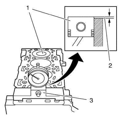
    2027918
  1. Align the TDC of the piston (1).
  2. Clean the cylinder block sealing surface and piston (1).
  3. Measure the piston projection thickness (2) using the GE-571-B gauge (3).
  4. Repeat the measuring process on the other cylinders and average the measured piston projection values.
  5. Choose the cylinder head gasket specifications:
  6. • Piston Protrusion 0.194-0.337 mm (0.008-0.013 in)
      Gasket Thickness 1.1 mm (0.043 in)
    • Piston Protrusion 0.337-0.44 mm (0.013-0.017 in)
      Gasket Thickness 1.2 mm (0.047 in)
    • Piston Protrusion 0.44-0.542 mm (0.017-0.021 in)
      Gasket Thickness 1.3 mm (0.051 in)

    2027915

    Note: Ensure that the engine block and cylinder head surface are clear of oil, grease and old gasket material.

  7. Clean the cylinder head bolt holes.
  8. Install a NEW cylinder head gasket (2).
  9. Install the cylinder head (3).
  10. Caution: Refer to Fastener Caution in the Preface section.

    Caution: Refer to Torque-to-Yield Fastener Caution in the Preface section.
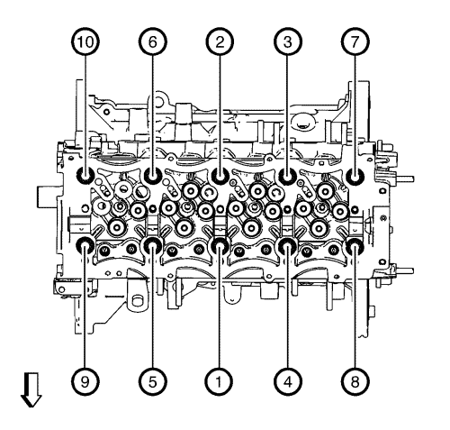

    2027917

    Note: Always use new cylinder head bolts.

  11. Install the 10 NEW cylinder head bolts.
  12. Tighten the 10 cylinder head bolts in a sequence as shown in the graphic.
  13. Tighten the 10 NEW cylinder head bolts in three passes:
  14. 11.1. First pass in sequence to 65 N·m (48 lb ft).
    11.2. Second pass in sequence to an additional 120 ° using the EN-45059 meter .
    11.3. Third pass in sequence to an additional 120 ° using the EN-45059 meter .

    2028272
  15. Install the charge air cooler inlet hose (2) to the turbocharger (1).
  16. Install the charge air cooler inlet hose clamp (3).
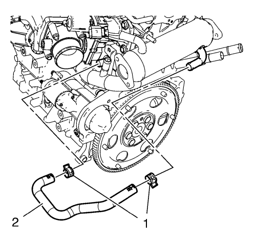
  17. 2027736
  18. Install the EGR manifold cooling feed hose (2).
  19. Install the 2 hose clamps (1).

  20. 2027737
  21. Install the EGR manifold cooling return hose (1).
  22. Install the 2 hose clamps (2).

  23. 2028279
  24. Install the charge air cooler outlet hose (3) to the throttle body (1).
  25. Install the charge air cooler outlet air hose clamp.
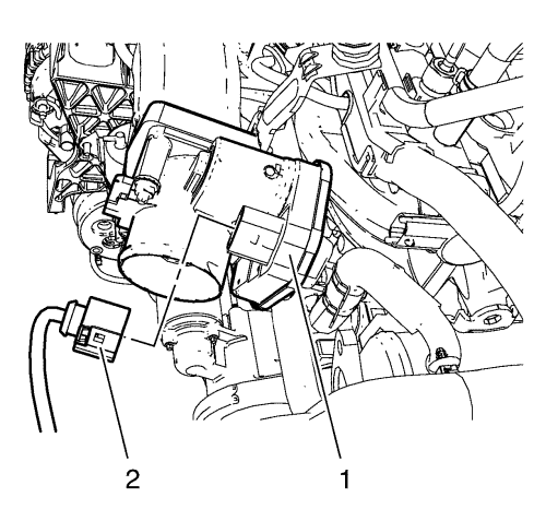
  26. 2027084
  27. Install the wiring harness plug (2) to the electronic throttle actuator control module (1).
  28. Install the fuel hose -- fuel injection pump to fuel feed block. Refer to Fuel Hose Replacement - Fuel Injection Pump to Fuel Feed Block .
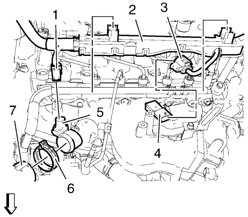
  29. 2028263
  30. Install the radiator inlet hose (7).
  31. Install radiator inlet hose clamp (6).
  32. Install the wiring harness (2).
  33. Install the coolant temperature sensor wiring harness plug (1).
  34. Install inlet air pressure and temperature sensor wiring harness plug (3).
  35. Install oil level indicator tube. Refer to Oil Level Indicator and Tube Installation .
  36. Install the timing belt. Refer to Timing Belt Replacement .
  37. Install the camshaft cover. Refer to Camshaft Cover Replacement .
  38. Install the turbocharger oil return pipe. Refer to Turbocharger Oil Return Pipe Replacement .
  39. Install the turbocharger oil feed pipe. Refer to Turbocharger Oil Feed Pipe Replacement .
  40. Install the catalytic converter. Refer to Catalytic Converter Replacement : 1.4L LUH and LUJ → 1.6L LXT,L2W → 1.6L LDE, LXV, 1.8L 2H0, and LUW → 2.0L Diesel LLW .
  41. Install the air cleaner outlet front duct. Refer to Air Cleaner Outlet Front Duct Replacement .


© Copyright Chevrolet. All rights reserved