Engine Replacement
Removal Procedure
- Remove the engine sight shield. Refer to Engine Sight Shield Replacement .
- Remove the battery tray. Refer to Battery Tray Replacement .
- Relieve the fuel system pressure. Refer to Fuel Pressure Relief .
- Discharge the air conditioning (A/C) system. Refer to Refrigerant Recovery and Recharging .
- Drain the engine coolant from the cooling system. Refer to Cooling System Draining and Filling .
- Remove the air cleaner assembly. Refer to Air Cleaner Assembly Replacement .
- Disconnect the engine control module (ECM). Refer to Engine Control Module Replacement .
- Disconnect the brake booster vacuum hose from the booster.
- Disconnect the engine fuel hose/pipes from the chassis fuel hose/pipes. Refer to Metal Collar Quick Connect Fitting Service .
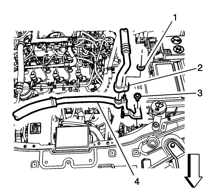
- Remove the evaporator outlet hose nut (1).
- Remove the evaporator outlet hose (2).
- Remove the air conditioning compressor hose bolt (3) from the electronic control module bracket.
- Remove the air conditioning compressor hose (4) from the electronic control module bracket.
- Using mechanic's wire, retain the radiator assembly to the core support.
- Remove the front bumper cover. Refer to
Front Bumper Fascia Replacement : Long Body → Short Body .
- Remove the air conditioning compressor hose bolt (1) from the condenser.
- Remove the compressor hose (2) from the condenser.
- Disconnect the range select cable from the range select lever if equipped. Refer to Range Selector Lever Cable Replacement .
- Disconnect the manual gearbox shift lever cable if equipped.
- Disconnect the transmission electrical connectors if equipped.
- Disconnect the heater hoses from the engine. Refer to
Heater Inlet Hose Replacement : Diesel → V6 → LE5 .
- Remove the radiator inlet hose. Refer to
Radiator Inlet Hose Replacement : Diesel → V6 → LE5 .
- Raise and support the vehicle. Refer to Lifting and Jacking the Vehicle .
- Remove the radiator outlet hose. Refer to
Radiator Outlet Hose Replacement : Diesel → V6 → LE5 .
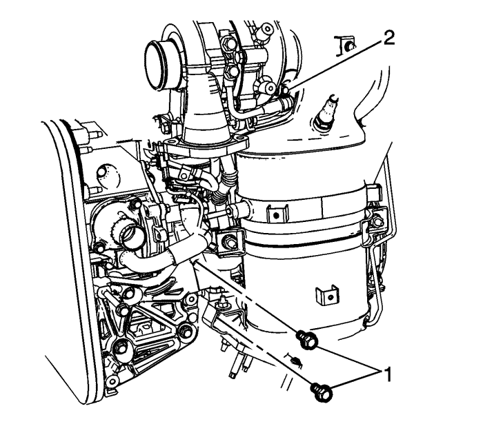
- Remove the exhaust mounting bolts (1) and loosen the turbocharger-to-diesel particulate clamp nut (2).
- Remove the diesel particulate filter (2) and discard the gasket (1). Refer to
Exhaust Particulate Filter Replacement : LNQ .
- Install the engine support adapters to the engine. Refer to Engine Support Fixture .
- Disconnect the transaxle oil cooler lines from the transaxle and remove the seals. Refer to Fluid Cooler Inlet Hose Replacement and Fluid Cooler Outlet Hose Replacement .
- Cap the transaxle oil cooler lines and plug the transaxle oil cooler line fittings to prevent loss of transmission fluid.
- Remove the front tyres. Refer to Tyre and Wheel Removal and Installation .
- Remove the right and left engine splash shields. Refer to Engine Splash Shield Replacement .
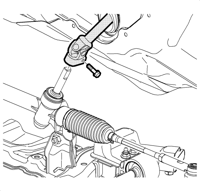
- Remove the steering intermediate shaft pinch bolt and discard the bolt.
- Disconnect the steering intermediate shaft from the steering gear.
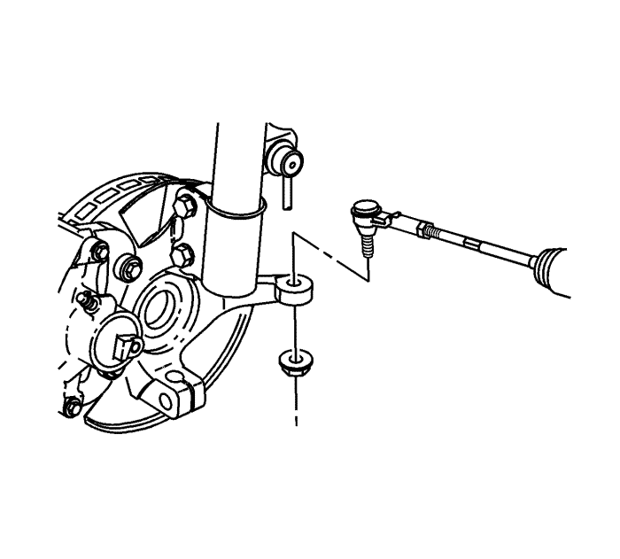
- Remove the right and left outer tie rod ends from the steering knuckles. Refer to Steering Linkage Outer Track rod Replacement .
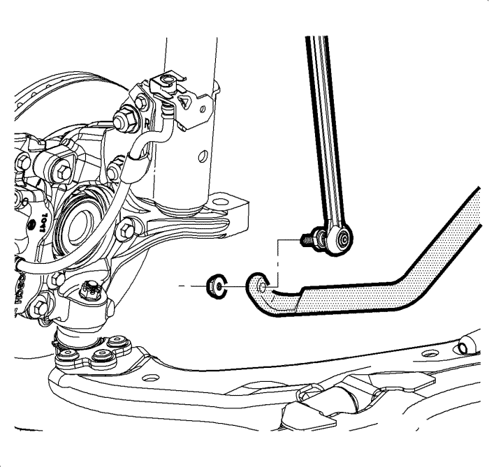
- Remove the right and left stabilizer shaft links from the stabilizer shaft. Refer to Stabilizer Shaft Link Replacement .
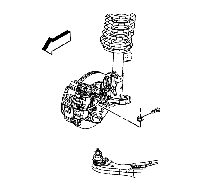
- Remove the right and left lower ball joints from the steering knuckles. Refer to Lower Control Arm Replacement .
- On front wheel drive (FWD) models, place a drain pan under the transaxle then separate the right and left front wheel drive shafts from the transaxle. Refer to Front Wheel Drive Shaft Replacement .
- On all wheel drive (AWD) models, remove the rear wheel driveshaft. Refer to Rear Wheel Drive Shaft Replacement .
- Remove the starter motor. Refer to
Starter Replacement : LNQ → LF1 → LE5 .
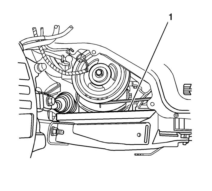
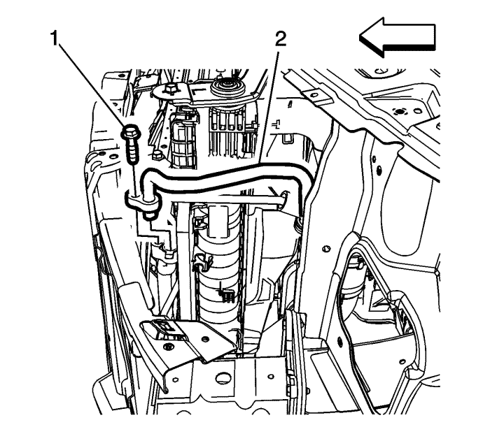
- On all models, place a block of wood (1) between the frame and the engine sump in order to support the engine once the bolts are removed from the right engine mount.
- Lower the vehicle.
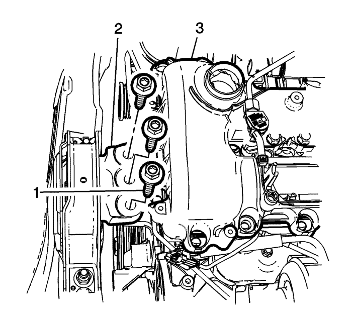
- Remove the bolts (2) that secure the right engine mount (1) to the engine (3).
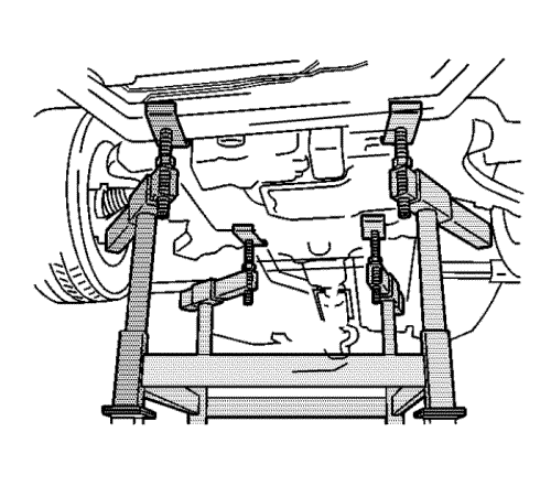
- Place a universal frame support fixture or axle stands under the frame.
Note: Ensure the vehicle body is secured to the hoist.
- Lower the vehicle until the frame contacts the frame support fixture or axle stands.
- Disconnect the wiring harness retaining clips near the right and left damper towers.
- Remove the drivetrain and front suspension frame reinforcement. Refer to Drivetrain and Front Suspension Frame Reinforcement Replacement .
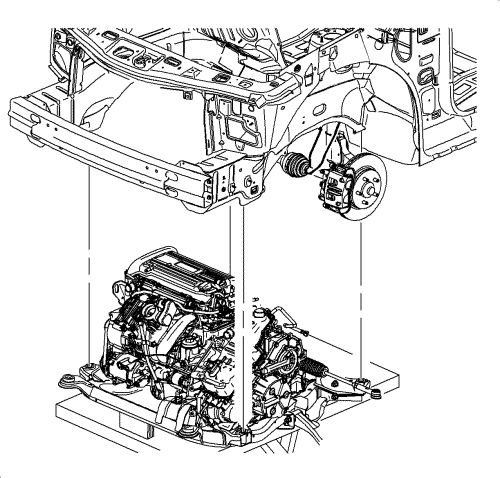
- Position the engine support table under the powertrain assembly.
- With the table positioned, fully raise the table to contact with the powertrain assembly.
- Remove the cradle bolts.
Note: During the powertrain removal, support the vehicle body by placing a jack at the rear of the vehicle.
- Slowly raise the vehicle until the powertrain assembly is clear of the vehicle.
- Remove the front transmission mount from the engine. Refer to Transmission Front Mount Replacement .
- Install the engine lift to the powertrain assembly.
- Separate the engine from the transmission on the floor.
- Lift the engine assembly from the cradle and place on the floor.
- Transfer parts as needed.
Installation Procedure
- Align the engine to the transmission.
Caution: Refer to Fastener Caution in the Preface section.
- Install the upper transmission-to-engine mounting bolts and tighten to 75 N·m (55 lb ft).
- Install the front transmission mount to the engine. Refer to Transmission Front Mount Replacement .
- Install wood blocks between the engine and cradle.
- Install the powertrain assembly to the vehicle.
- Install NEW frame-to-body bolts and tighten to 155 N·m (114 lb ft).
- Install the drivetrain and front suspension frame reinforcement. Refer to Drivetrain and Front Suspension Frame Reinforcement Replacement .
- Raise the vehicle up away from the frame support fixture or axle stands and remove the support fixture or axle stands from under the vehicle.
- Lower the vehicle.
- Install the bolts (1) that secure the right engine mount (2) to the engine (3) and tighten to 50 N·m (37 lb ft).
- Raise the vehicle.
- Remove the block of wood (1) between the frame and the engine sump used to support the engine while the bolts were removed from the right engine mount.
- On AWD models, install the rear wheel driveshaft. Refer to Rear Wheel Drive Shaft Replacement .
- On FWD models, install the right and left front wheel drive shafts into the transaxle. Refer to Front Wheel Drive Shaft Replacement .
- On all models, install the right and left lower ball joints to the steering knuckles. Refer to Lower Control Arm Replacement .
- Install the right and left stabilizer shaft links to the stabilizer shaft. Refer to Stabilizer Shaft Link Replacement .
- Install the right and left tie rod ends to the steering knuckles. Refer to Steering Linkage Outer Track rod Replacement .
- Connect the steering intermediate shaft to the steering gear.
- Install a NEW pinch bolt to the steering intermediate shaft and tighten to 34 N·m (25 lb ft).
- Install the right and left engine splash shields. Refer to Engine Splash Shield Replacement .
- Install the front tyres. Refer to Tyre and Wheel Removal and Installation .
- Install new seals and connect the transaxle oil cooler lines to the transaxle. Refer to Fluid Cooler Inlet Hose Replacement and Fluid Cooler Outlet Hose Replacement .
- Install the exhaust mounting bolts (1) and loosen the turbocharger-to-diesel particulate clamp nut (2).
- Install the diesel particulate filter (2) and discard the gasket (1). Refer to
Exhaust Particulate Filter Replacement : LNQ .
- Install the radiator outlet hose. Refer to
Radiator Outlet Hose Replacement : Diesel → V6 → LE5 .
- Lower the vehicle.
- Install the radiator inlet hose. Refer to
Radiator Inlet Hose Replacement : Diesel → V6 → LE5 .
- Connect the heater hoses to the engine. Refer to
Heater Inlet Hose Replacement : Diesel → V6 → LE5 .
- Connect the transaxle shift control cable to the transaxle. Refer to Range Selector Lever Cable Replacement .
- Install the A/C compressor hose assembly to the compressor. Refer to
Air Conditioning Compressor Hose Replacement : Diesel → L4 → V6 .
- Connect the transmission electrical connectors.
- Install the air conditioning compressor hose (4) to the electronic control module bracket.
- Install the air conditioning compressor hose bolt (3) to the electronic control module bracket and tighten to 20 N·m (15 lb ft).
- Install the evaporator outlet hose (2).
- Install the evaporator outlet hose nut (1) and tighten to 20 N·m (15 lb ft).
- Install the air cleaner assembly. Refer to Air Cleaner Assembly Replacement .
- Connect the brake booster vacuum hose.
- Install the battery tray. Refer to Battery Tray Replacement .
- Connect the negative battery cable. Refer to Battery Negative Cable Disconnection and Connection .
- Fill the engine with engine oil. Refer to Engine Oil and Oil Filter Replacement .
- Fill the engine with coolant. Refer to Cooling System Draining and Filling .
- Check the transaxle fluid level. Refer to Transmission Fluid Replacement .
- Charge the A/C system. Refer to Refrigerant Recovery and Recharging .
- Prime the fuel system.
| 44.1. | Cycle the ignition ON for 5 seconds then OFF for 10 seconds. Repeat cycling twice. |
| 44.2. | Crank the engine until it starts. The maximum starter motor cranking time is 20 seconds. |
| 44.3. | If the engine does not start, repeat the steps. |
- Perform the Crankshaft Position System Variation Learn procedure. Refer to Crankshaft Position System Variation Learn .
| © Copyright Chevrolet. All rights reserved |


